


- EOL

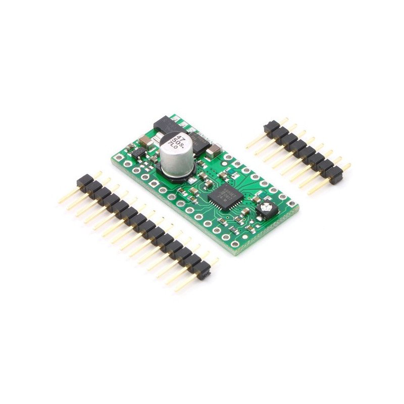


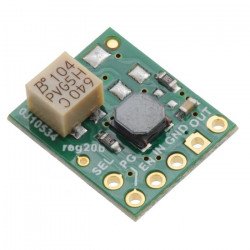
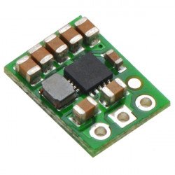
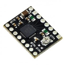
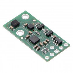
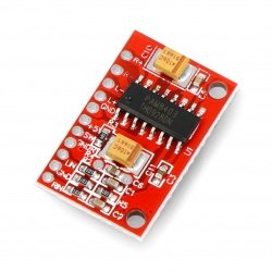
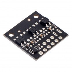
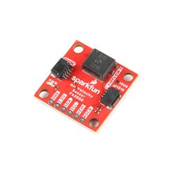
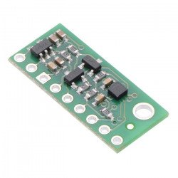
Polol module with a two-channel direct current motor controller. The system is powered from 4.5 to 13.5 V and has a built-in regulator. Continuous current per channel is 1 A, when both channels are connected the value increases to 2 A.
|
Attention! The sale of the product has been completed. Check others in thiscategory. |

The system allows to control the stepper motor by means of a device allowing to generate logical states e.g.Arduino,STM32Discovoery,Raspberry PiThe Polol module is characterized by very simple operation. It has a built-in voltage regulator, thanks to which there is no need to provide separate power supply for the logical part.
To rotate the engine one step at a time, the STEP output must be set to high (logical one), the next sequence of zeroes and ones will move the engine one step at a time, and so on. The direction is selected by entering the appropriate state on the DIR output (e.g. low state - clockwise rotation, low state - opposite). The controller also has the possibility to select theresolution ofthe motor.
To control the bipolar stepper motor, connect the system as shown in the figure below. When controlling a unipolar motor, refer to themanual. If the nominal motor voltage is lower than the required power supply for the controller (8 V),set the current limitmanually using a potentiometer.

To supply the logical part of the module, a voltage range of 3 V to 5.5 V is required, which has to be connected to the VDD pin by connecting an external source or by connecting to an adjacent 5 V or 3.3 V output. The motor supply voltage from 8 V to 35 V must be fed to the VMOT pin.
The system can be controlled by motors with a nominal voltage lower than the required 8 V. For this purpose, the maximum current consumption mustbe limitedby means of a potentiometer so as not to exceed the permissible motor current. For example, for a motor with a resistance of 5 Ω per coil and a current consumption of 1 A, the nominal supply voltage is 5 V. When supplying 12 V, the current should be limited so that it does not exceed 1 A.
|
Attention! Connecting and disconnecting the motor while the controller is on can damage the system. |
Step size is selected using MS1, MS2, MS3 inputs. The possible settings are shown in the table below. Inputs MS1, MS2 and MS3 have an internal pull-down resistor.
| MS1 | MS2 | MS3 | Resolution |
|---|---|---|---|
| low | low | low | Full step |
| high | low | low | 1/2 step |
| low | high | low | 1/4 step |
| high | high | low | 1/8th step |
| high | high | high | 1/16 step |
One pulse given on the STEP pin causes one motor step in the direction selected by giving the appropriate logical state on the DIR pin. The STEP and DIR outputs are not pulled up internally. If the motor is to turn in only one direction, the DIR pin can be permanently connected to VCC or GND.

The system has three more inputs to control power consumption:RESET, SLEEP and ENABLEare described inthe documentation.
The system can be controlled by motors with a nominal voltage lower than the required 8 V. For this purpose, the maximum current consumption mustbe limitedby means of a potentiometer so as not to exceed the permissible motor current. For example, for a motor with a resistance of 5 Ω per coil and a current consumption of 1 A, the nominal supply voltage is 5 V. When supplying 12 V, the current must be limited so that it does not exceed 1 A.
The A4988 module allows for active current limitation with a potentiometer. One of the ways to introduce the limitation is to set the controller to full step mode and to measure the current flowing through one coil without giving a signal to the STEP input. The measured current is 70% of the set limit (both coils are always on and limited to 70% in full step mode). Another way is to measure the voltage at the REF output (marked with a circle on the PCB) and calculate the current limit (measuring resistors are 0.05Ω). For more details seeA4988documentation.
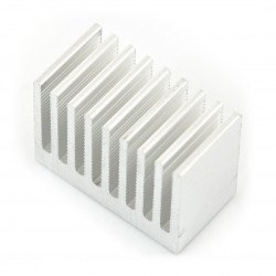
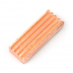
The plate is designed to dissipate the heat at a current consumption of about 1A per coil. If the current is much higher, an external heat sink should be used, which can be mountedwiththermally conductive adhesive.
Useful links |
| Package width | 0.001 cm |
| Package height | 0.001 cm |
| Package depth | 0.001 cm |
| Package weight | 0.001 kg |
Be the first to ask a question about this product!


