


- EOL

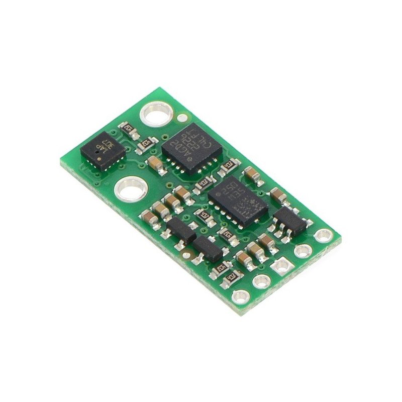


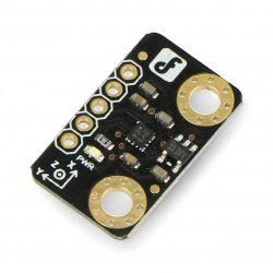
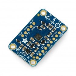
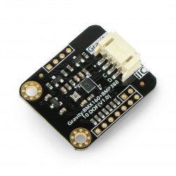
Sensor for measuring acceleration, magnetic field, angular speed and height. It is a combination of a 3-axis accelerometer, magnetometer, gyroscope and barometer. It communicates via the I2C bus.
|
Attention! Product replaced by a new version:AltIMU-10 v3 gyroscope, accelerometer, compass and altimeter. |
 Specification .
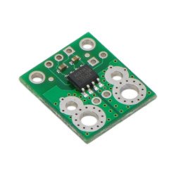
AltIMU-10 module is a 3-axis accelerometer, 3-axis magnetometer (LSM303), 3-axis gyroscope (L3GD20) and barometer (LPS331).With these sensors it is possible to create a complete AHRS (attitude and heading reference system), i.e. to determine the position of an object in three-dimensional space. Data from the barometer are easily converted to height, the gyroscope allows to track the rotation of the object and the accelerometer together with the magnetometer compensate the gyroscope drift and determine the absolute reference point.
All sensors communicate digitally via the I2C bus. The module has a voltage regulator and the necessary passive elements. The leads are the popular goldpin connectors, which allow the sensor to be connected bywires ordirectly connected to the contact plate.

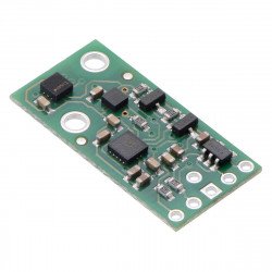
AltIMU-10 is pin-compatible with MinIMU-9 v2 module. It has the same functions with the addition of a digital barometer that can be used as a height sensor. Correctly written code for MinIMU-9 v2 will work with AltIMU-10.
|
Arduino compatible product The manufacturer has prepared libraries for the L3G gyroscope, LSM303accelerometerandLPS331barometer, whichallowfor simple sensor operation with Arduino. |
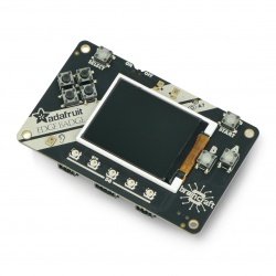
In order to show the capabilities of the IMU module, a sample program for Arduino is available. It uses data from AltIMU-10 to determine coordinates in three axes X, Y, Z to visualize the object in 3D space, as shown in the figures above. The software is based on a project by Jordi Munoz, William Premerlani, Jose Julio and Doug Weibel.

Visualization of an object in 3D space.
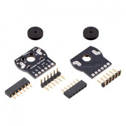
The sensor has five goldpin connectors - 2.54mm raster (included).

PIN |
Description |
| SCL | I2C bus clock line. The high state is equal to the VIN voltage. Low GND. |
| SDA | I2C bus data line. High state equals VIN voltage. Low GND. |
| GND | System mass potential |
| VIN | Supply voltage from 2.6V to 5.5V |
| VDD | If the supply voltage is higher than 3.3V, the output can serve as a 3.3V output with a current capacity up to 150mA. When the power supply voltage is in the range of 2.5V - 3.3V, connect it to the VDD output. |
The accelerometer, magnetometer, gyroscope and barometer, located in the module, have 7-bit addresses. They are set to the appropriate address:
The bus works correctly at 400MHz, higher values may work correctly but have not been tested.
All necessary information on communication and sensor handling of the AltIMU-10 can be found inthe documentation ofeach sensor. Below are some of the most important facts:
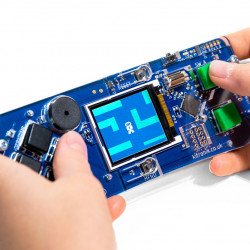
Visualization of orientation in space based on readings from the IMU module.
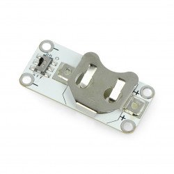
The system is small in size, its outline fits into a rectangle of dimensions: 25.4 x 12.7 mm. The assembly is done with a 2.18mm internal diameter hole.

The system includes, among others, voltage stabilizers, filtering capacitors, pull-up resistors (e.g. I2C bus lines) and other passive elements facilitating the use of IMU sensors.

Useful links |
| Package width | 0.001 cm |
| Package height | 0.001 cm |
| Package depth | 0.001 cm |
| Package weight | 0.001 kg |
Be the first to ask a question about this product!


