


- EOL


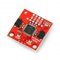
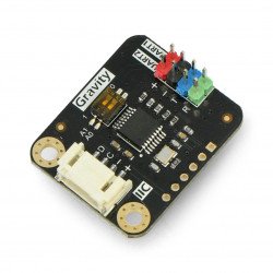
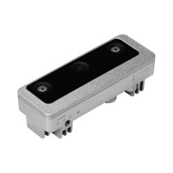
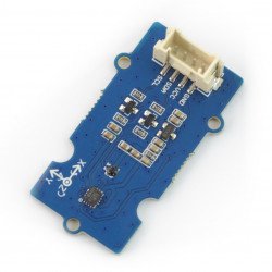
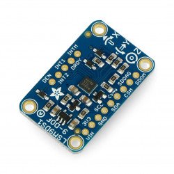
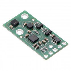
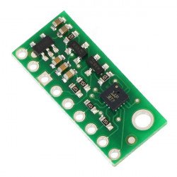
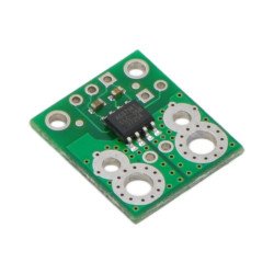
Sensor for measuring angular speed in three axes. It has a choice of measuring range: to±250 °/s, ±500 °/s,±2000 °/s. It communicates via the I2C or SPI bus and has an integrated voltage regulator.
|
Attention! Product replaced by a new version:L3GD20H 3-axis digital I2C SPI gyroscope. |
 Specification
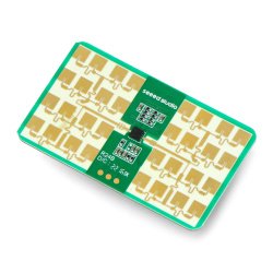
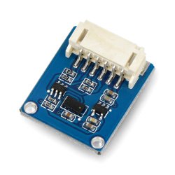
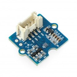
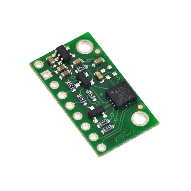
The sensor is used to measure angular speed in three axes. The module has a gyroscopeL3GD20( datasheet) fromSTcompanytogether with voltage regulator and necessary passive elements.
|
The L3GD20 system has a resonator of higher frequency than the previous model L3G4200D. This reduces interference and vibration generated by audio frequency devices. |
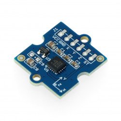
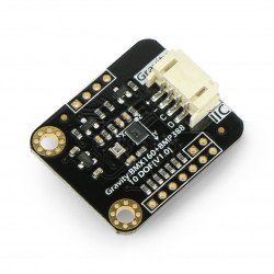
We also offer a MinIMU-9 module containing a 3-axis accelerometer, magnetometer and gyroscope.
|
Product compatible with Arduino The manufacturer has prepared a librarythat makes it easier forArduino users to use the module. |
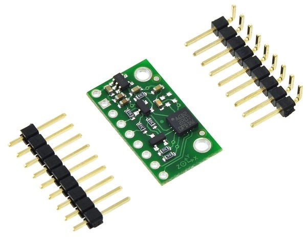
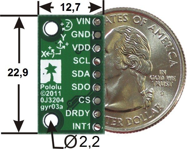
The sensor has nine leads for mounting goldpin-type connectors - 2.54mm raster (included). On customer's request we can solder the strip.
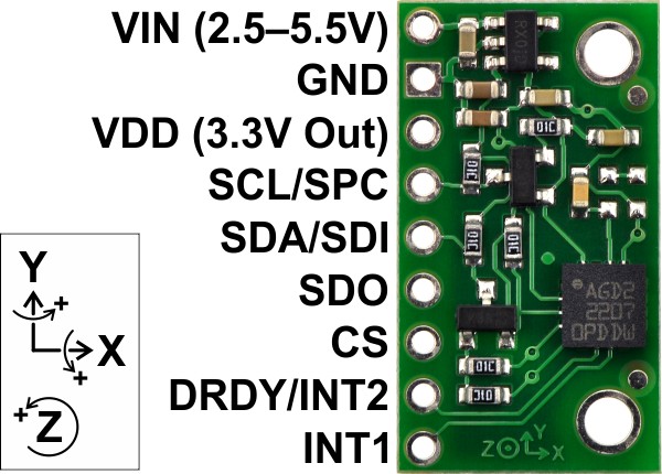
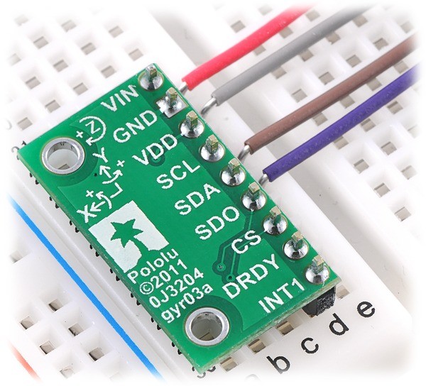
| PIN | Description |
| VIN | Supply voltage 2.5 V - 5.5 V |
| GND | System mass potential |
| VDD | 3.0 V regulator output |
| SCL | Clock line I2C |
| SDA | I2C data line |
| SPC | Clock line SPI |
| SDI | SPI data line |
| SDO | SPI data line or address selection for I2C |
| CS | Enabling SPI by default pulled up to VCC (set to I2C), to enable the SPI interface you must pull up to ground |
| DRDY/INT2 | Data read ready / interrupt from FIFO queue |
| INT1 | Configurable interruption |
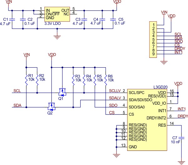
The communication interface is selected by setting the logical state on the CS output, which is internally pulled up to the VDD. This means that by default, the system communicates via the I2C bus. To select the SPI option, the CS pin must be shorted to ground.
I2C
The chip has a 7-bit address, whose last bit (LSB) is configurable by outputting SDO. By default, the SDO is pulled to VCC via a 10k ohm resistor, which sets the address to1101011b. If there is a conflict with another device, the address can be changed by connecting SDO to ground. This will change the last bit of LSB to 0.The specific transmission and register description can be found in the system documentation.
The manufacturer states that the system operates flawlessly at 400 kHz (I2C fast mode). Above this value, transmission interference may occur.
SPI
To select communication via SPI, the CS pin should be connected to ground. Detailed transmission and register description can be found in thesystemdocumentation.
| Package width | 0.001 cm |
| Package height | 0.001 cm |
| Package depth | 0.001 cm |
| Package weight | 0.001 kg |
Be the first to ask a question about this product!


