


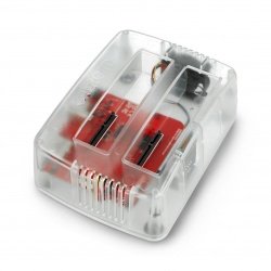


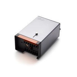


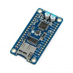


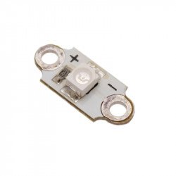


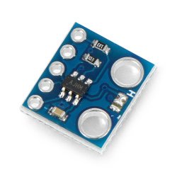
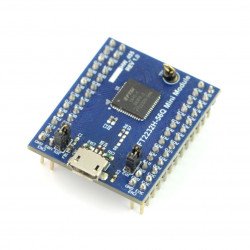


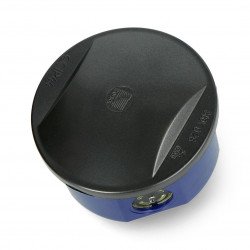


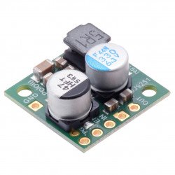


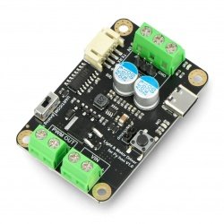


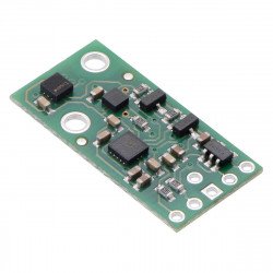

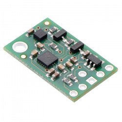


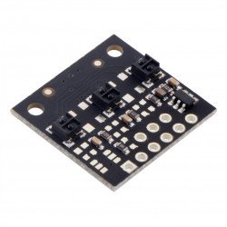
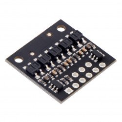


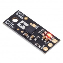


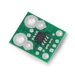

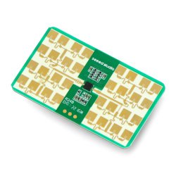


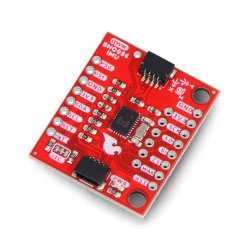
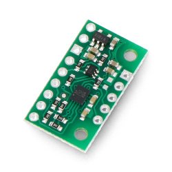


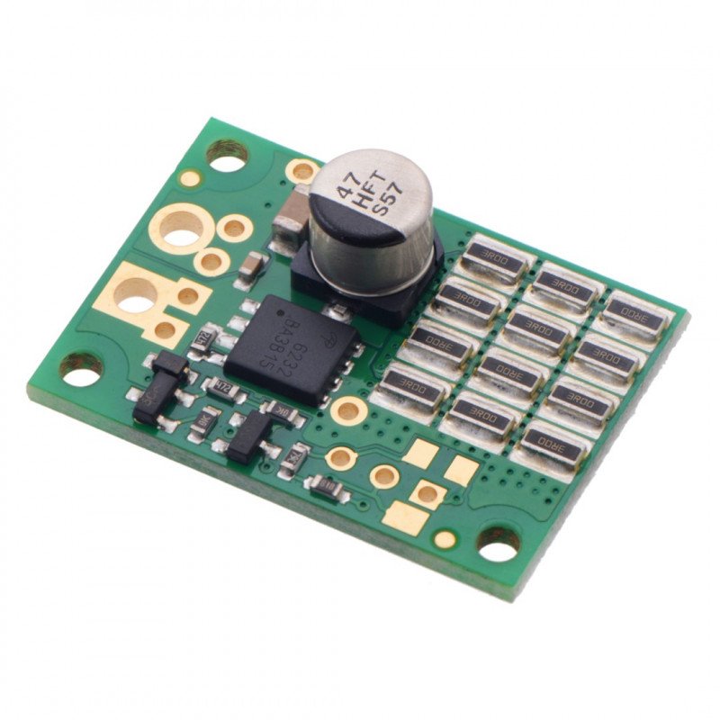


The shunt regulator can protect the power supplies from voltage spikes generated by the motor controllers connected to them. This version has a fixed value of 13.2 V, a shunt resistance of 1.33 Ω and 12 SMT shunt resistors located on one side of the PCB. An external potentiometer can be used to set the voltage.
The shunt regulator canprotectpower suppliesfrom voltage spikes generated bymotor controllersconnected to them. This version has a fixed value of13.2 V, a shunt resistance of1.33 Ωand12 SMT shunt resistorslocated on one side of the PCB. An externalpotentiometercan be used toset the voltage.
The regulator should be installed in parallel with thepower supplyfor proper operation. The supply voltage should be lower than the regulator voltage and the regulator should draw only resting current less than 0.5 mA. Any voltage pulses above the setting will cause the regulator to draw significantly more current, dissipating energy and limiting the range of voltage variation.
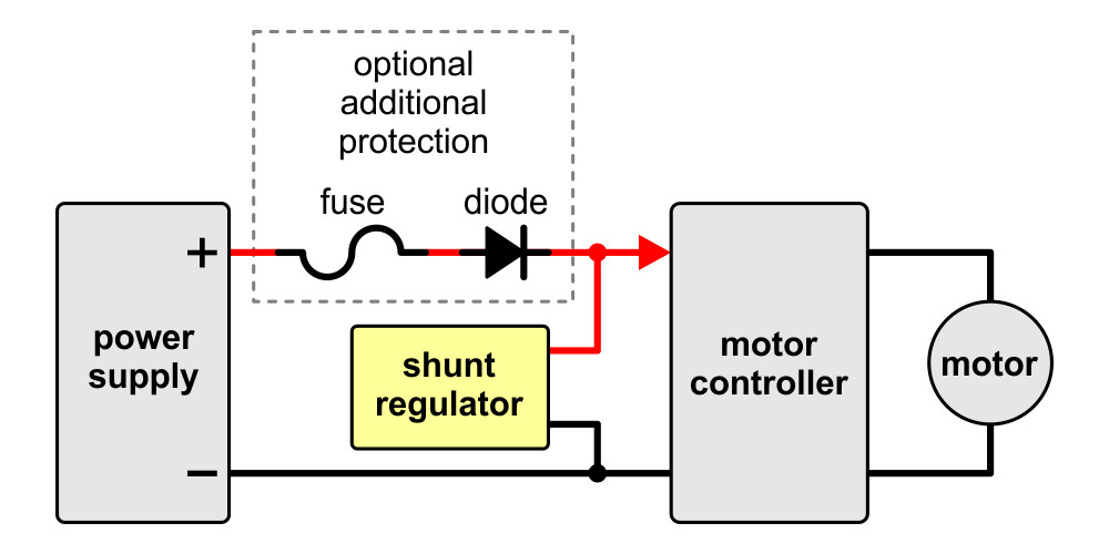
Shunt regulator wiring diagram between power supply and motor controller.
Next is a simplified schematic of a shunt regulator. The circuit monitors the voltage and controls theMOSFET, which allows current to flow through the shunt resistance, which sets the maximum current the device can absorb.

Simplified schematic of a shunt regulator.
All Pololu shunt regulators differ only in voltage value and resistance. The available versions can be found in the table below:
| Voltage | ||||||||
|---|---|---|---|---|---|---|---|---|
| 13,2 V | 26,4 V | 33,0 V | Fine adjustment LV | Fine adjustment of HV | ||||
| Power: | 3 W | |||||||
| 9 W | ||||||||
| 15 W | ||||||||

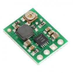
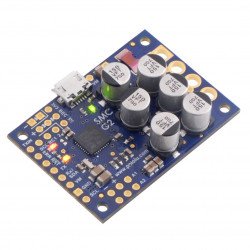
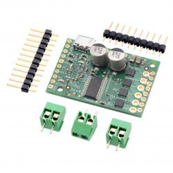
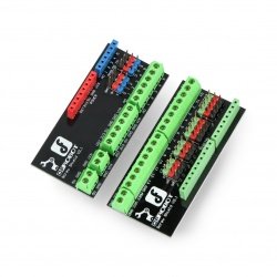
On the left is the lower appearance of the 3 W and 9 W regulator, while on the right is the 13 V, 1.50Ω, 15 Wregulator.
Note!
The power is primarily intended to indicate the relative average power consumption for a maximum of a few seconds. The boards are designed to clip occasional, short pulses. Prolonged application of voltage above the set point will destroy the regulator almost immediately (in less than a second).
The shunt regulator is available in two adjustable versions with multi-turn potentiometers. All fixed voltage versions can also be adjusted by adding a potentiometer on the board.
The two adjustable versions differ only in the shunt resistance and the mapping optimization of the voltage setting potentiometer.
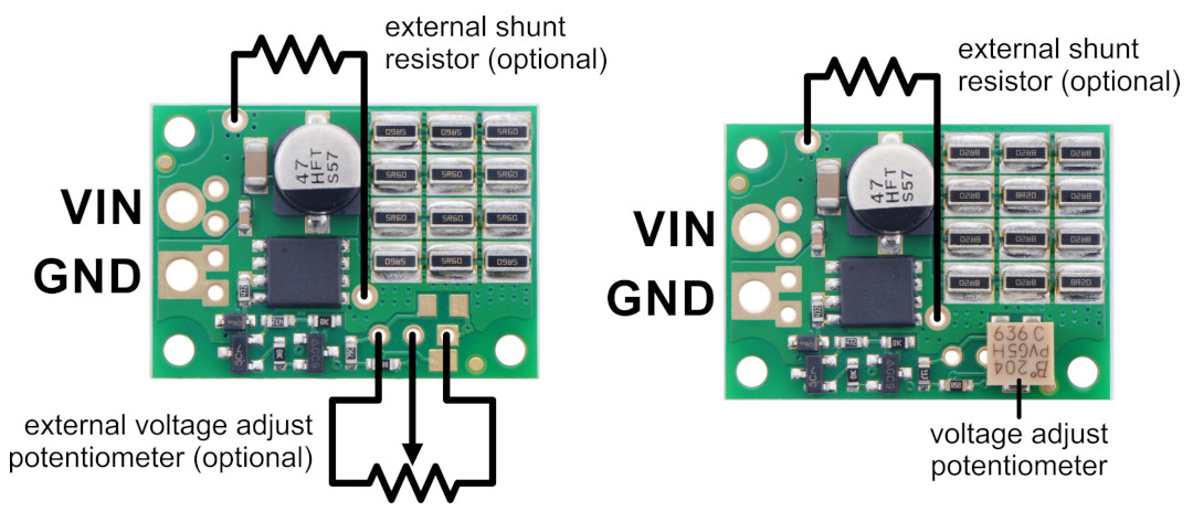
On the left are the leads for the fixed-voltage regulator, on the right are the leads for the adjustable-voltage regulator.
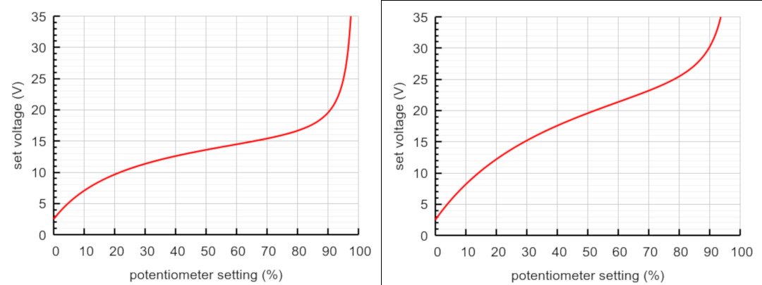
Schematics of the set voltage relative to the adjusted potentiometer:
Left side LV curve: 1.50Ω, 15 W. Right side HV curve: 4.10 Ω, 15 W.
The HV curve was obtained using a 200 kΩ potentiometerwith a 33.0 V plate, using a 200 kΩ potentiometer with low voltage fixed value plates will disturb the mapping by looking like an LV curve. (100 kΩ or lower value potentiometers can be used at the expense of higher resting current, since the full supply voltage is applied through this potentiometer.)
When setting the voltage with a potentiometer, or to check the exact voltage of any shunt regulator, connect a higher voltage with a current-limiting resistor of at least a few hundred Ω and measure the voltage on the regulator. (Without a current limiting resistor, the regulator would not work if it was set higher than the test supply voltage, and it would start to emit smoke if it was set below your supply voltage !) Typically, you should set the regulator at about 10% above your supply voltage.

In addition to linear voltage regulators and impulse regulators, one of the most common designs in electronic devices and control systems are shunt voltage regulators. In the simplest terms, the shunt voltage regulator operates on the principle of redirecting part of the current drawn from the power source to the ground of the electrical circuit. In typical constructions, the regulating element is a voltage divider built from a Zener diode, the anode of which is connected to ground and a resistor. Bipolar transistors are also used, in which the value of the emitter current conducting from the power source to the ground (through a resistor limiting the current flow) is proportional to the current controlling the transistor's base.
Electric motor controllers offer the possibility of smooth adjustment of rotational speed and changing the direction of rotation. Unfortunately, it turns out that serious damage can occur to the control system and the power supply of the motor when switching. The cause is the overvoltage impulses, which arise as a result of sudden current interruption in the circuit and consequently discharge of energy previously accumulated in the magnetic field of the motor magnet. Inclusion of the Pololu 3770 shunt regulator in the circuit solves this problem flawlessly, enabling trouble-free operation of the motor and the control and power supply systems.
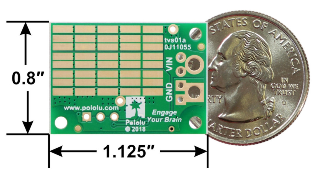
| Length | 29 mm |
| Width | 21 mm |
| Height | 8 mm |
| Voltage to | 13.2 V |
| Voltage from | 13.2 V |
| Voltage output from | 13.2 V |
| Output voltage to | 13.2 V |
| Current | 0.65 A |
| Stabilizer - Type2 | shunt |
Be the first to ask a question about this product!


