


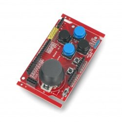


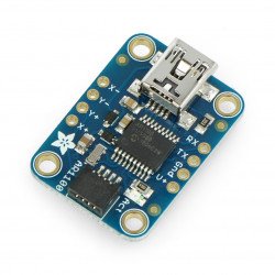


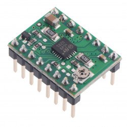

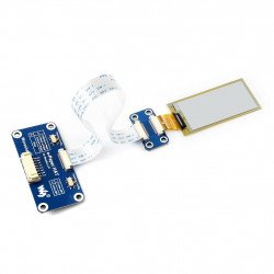


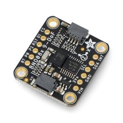


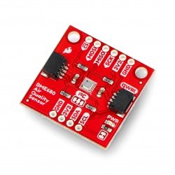

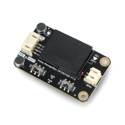


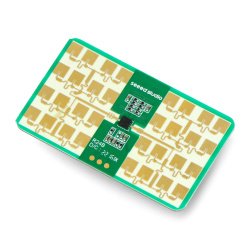
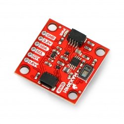


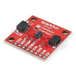


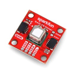

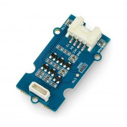


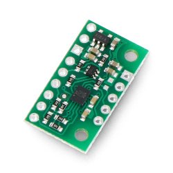


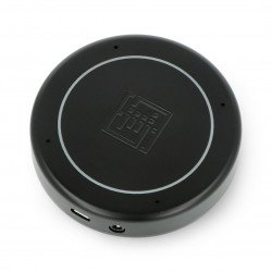


A radio transmitter operating on FM waves basing on the high-class Si4713 system. The device transmits within a radius of up to 10 m, it communicates via I2C interface, it works with a voltage from 3 V to 5 V. It also allows for the RDS / RBDS data to be transmitted and has a soldered audio Jack connectors.
A radio transmitter operating on FM waves basing on the high-class Si4713 system. The device transmits within a radius of up to 10 m, it communicates via I2C interface, it works with a voltage from 3 V to 5 V. It also allows for the RDS / RBDS data to be transmitted and has a soldered audio Jack connectors which allow you to connect the transmitted audio signal.
|
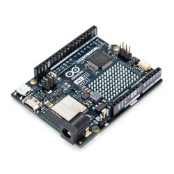
The product is compatible with Arduino Sample code can be found inthe user guide. |
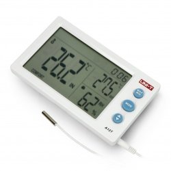
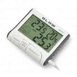
For receiving the signal transmitted through the transmitter of audio signal and of RDS / RBDS data, sufficient is just any radio receiver operating in the FM band, for example, in a car radio.
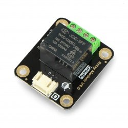
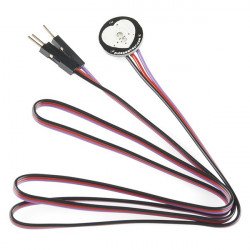
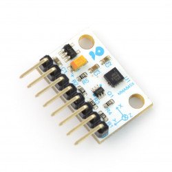
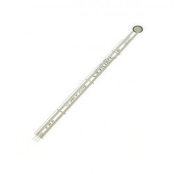
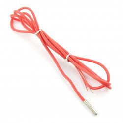
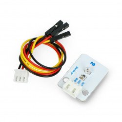
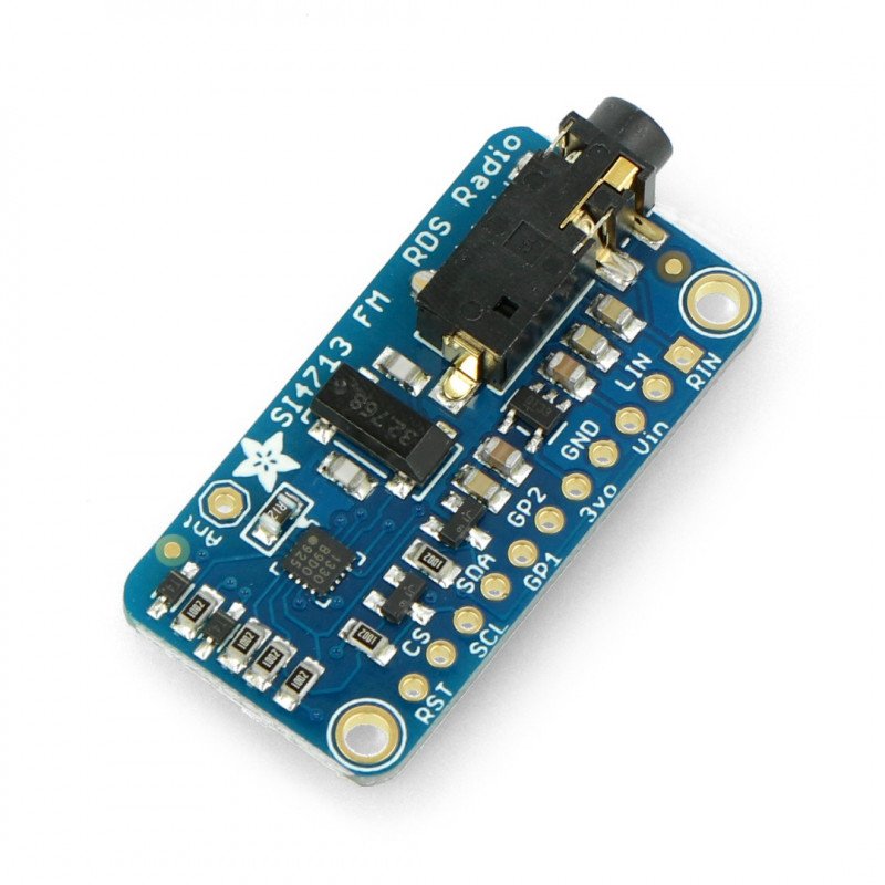
The set includesgoldpinconnectors,pitch of 2.54mm and the transmitting wire which must be self-soldered. The description of the individual pins are presented in the form of a table:
| Pin | Description |
|---|---|
| VIN | Supply voltage in the range from 3 V to 5 V. |
| GND | The ground of the system. |
| 3Vo | 3.3 V voltage regulator's output with the maximum current of up to 100 mA |
| LIN | Left audio channel - connected to the audio jack slot, it enables to connect the transmitted audio signal. |
| RIN | Right audio channel - connected to the audio jack, it enables to connect the transmitted audio signal. |
| RST | The reset is activated with the low status. The manufacturer recommends the reset of the system before starting the communication with the microcontroller. |
| CS | In the SPI mode, it is a chip select. For I2C, it is the choice of the bus address, by default, in a high status, it sets the address to 0x63. Indicating the low status, changes the address to 0x11. |
| SCL | Clock line of I2C interface. |
| SDA | Data line of I2C interface. |
| GP1 | Additional GPIO pin, which works with a voltage of 3.3 V. Be careful not to short the pin from GND or VCC at the start of the module. |
| GP2 | Additional GPIO pin is working with a voltage of 3.3 V. Be careful not to short the pin from GND or VCC at the start of the module. |
Useful links |
| Package width | 6.5 cm |
| Package height | 0.7 cm |
| Package depth | 6.5 cm |
| Package weight | 0.007 kg |
Be the first to ask a question about this product!


