


- EOL

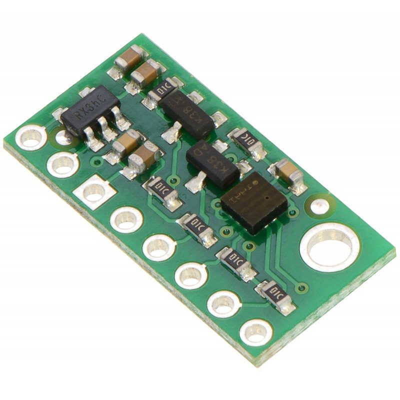


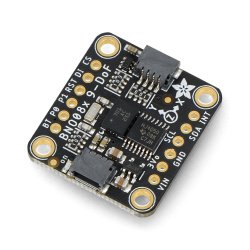
Sensor for measuring a pressure in the range from 26 kPa to 126 kPa with a accuracy at level of ± 0,02 kPa. The measurement result can be easily converted to altitude. In comparison to the version of the LPS331AP, sensor has a higher precision and reduced noise level.
|
Attention! The product has been discontinued. Check others products incategory. |
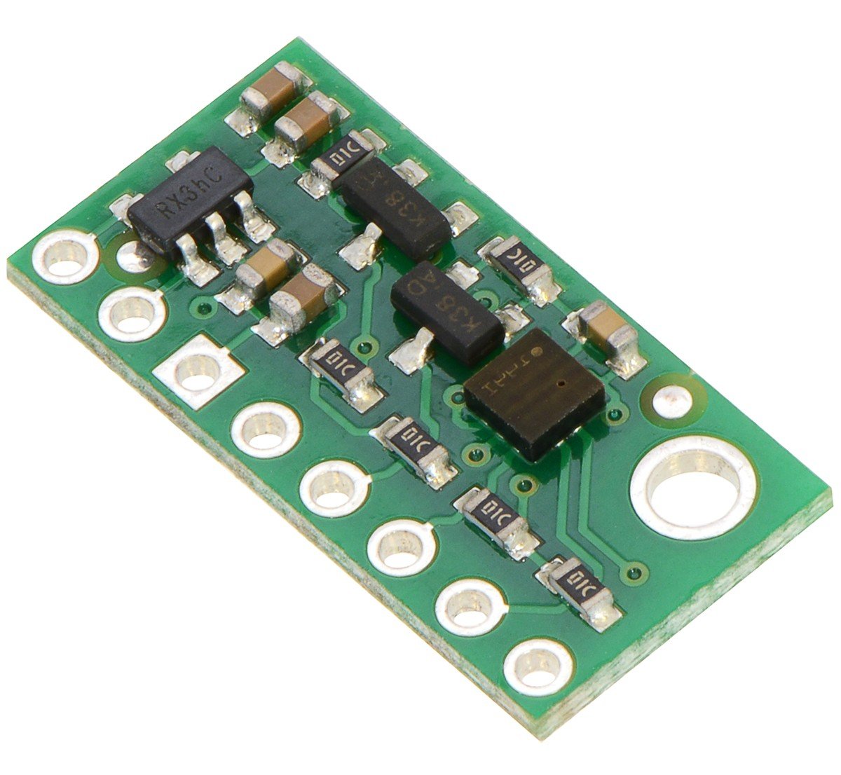
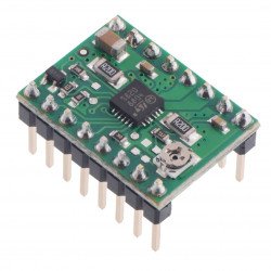
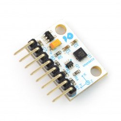
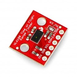
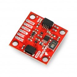
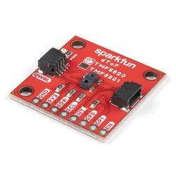
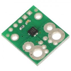
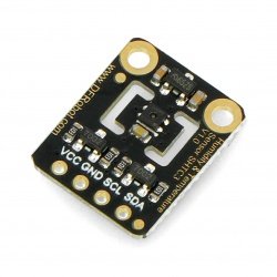
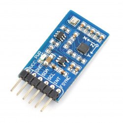
The module includes a pressure sensor MEMS LPS25H from the ST company, which operates in the range from 26 kPa to 126 kPa. Compared to the version of the LPS331AP, with which the pin is compatible, it is characterized by a higher accuracy (up to 0.02 kPa) and lower noise (0,001 kPa). It also has a built-in buffor FIFO, in which stored can be the measurement data before transmission. On the board are also required passive components and voltage regulator low-droput which enables the operation of the sensor with systems of 3.3 V and 5 V.
System LPS25H (documentation) has a built-in temperature compensation and a lot of configurable options, including: selectable resolutions, as well as two programmable external interrupts. The communication interface is I2C or SPI bus.
|
The product is compatible with Arduino The manufacturer has prepared an Arduino library for the sensor LPS25H which allows for the simple maintenance of the sensor, using the module of Arduino. |
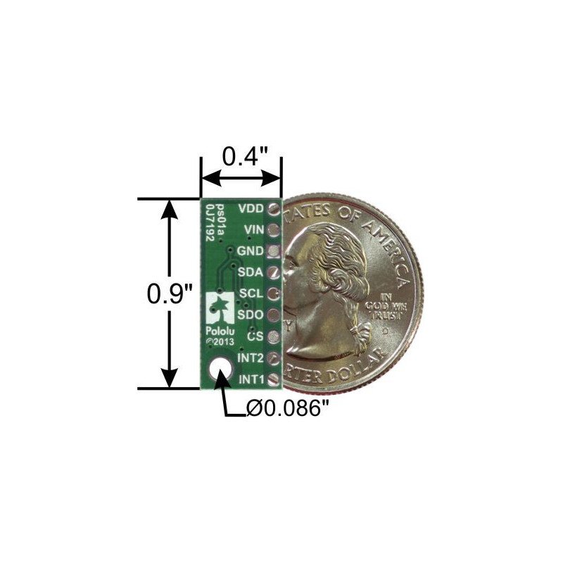
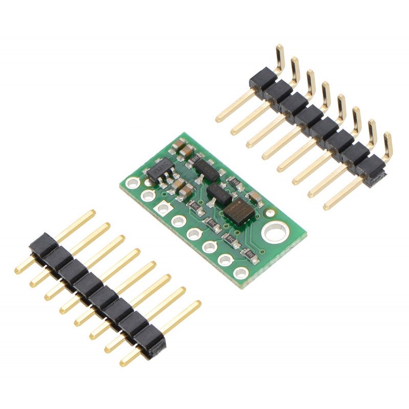
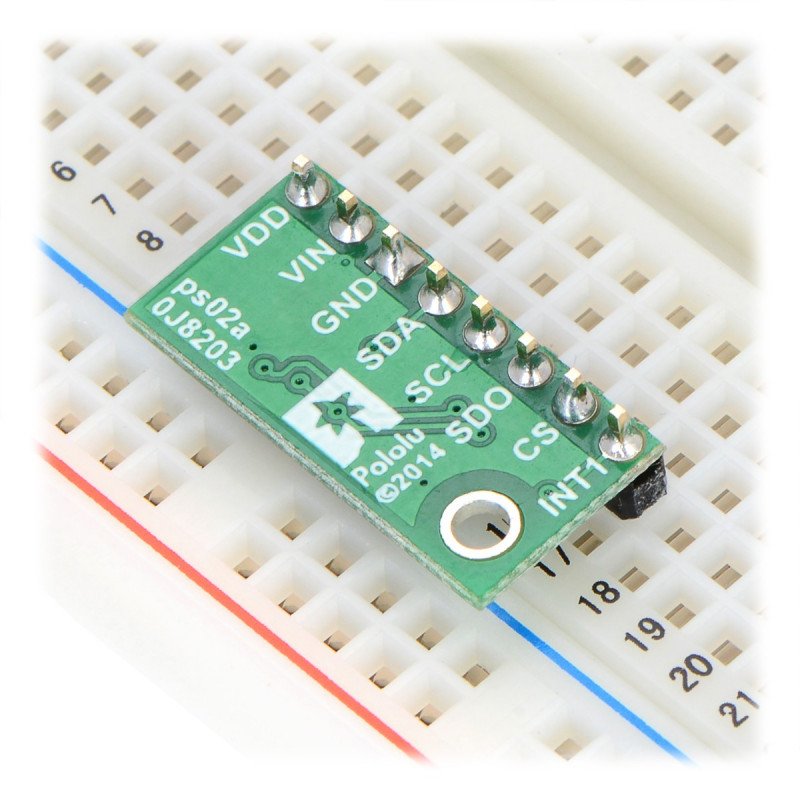
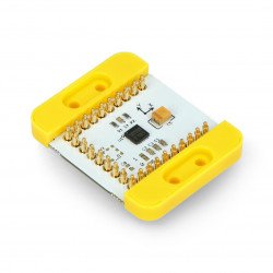
The sensor has eight pins for the installation of goldpin connectors - 2.54 mm pitch (included).
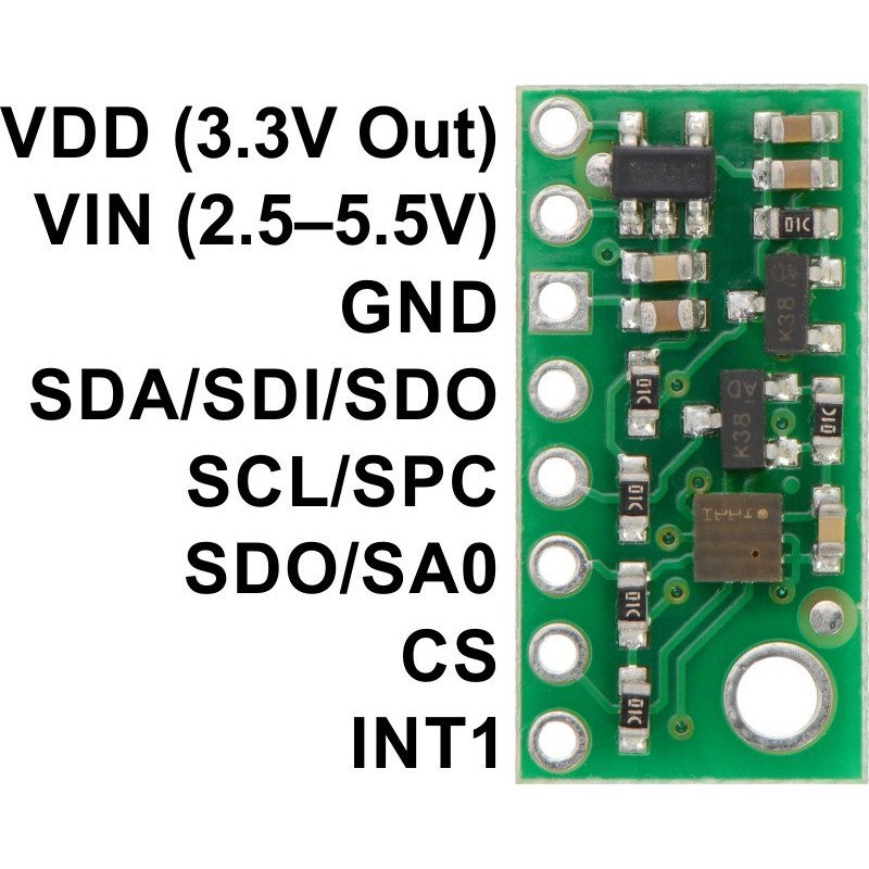
The power supply is in the range of 2.5 V to 5.5 V, it should be connected to pins VIN and GND. In the case of using the system powered with a voltage of 3.3 V, the VIN pin can be left disconnected, and the power supply should be brought directly to the system via pin VDD.
The system communicates via a digital I2C or SPI interface. Voltage of the logic signals of the bus must have the same value as the supply voltage supplied to VIN. In the case of using I2C bus, the SCL and SDA pins should be connected. SPI requires the connection of 4 pins: SDI, SDO, CS and SPC.


| PIN | Description< |
|---|---|
| SDA SDI SDO |
The data line of the I2C bus, the line of the input SPI data (SDO in 3-wire mode). High status is equal to the voltage VIN, low GND. |
| SCL SPC |
Clock line of the I2C bus. High status is equal to voltage VIN, low GND. |
| SDO SA0 |
The output data line of SPI bus (data-out) or change of address in case of I2C. High status is equal to VDD voltage, low GND. These pins do not have a voltage converter - they only work with a voltage of 3.3 V. |
| CS | Chip select - SPI Enable. The pin is by default in high status (active I2C interface) to begin to communicate in SPI, you must specify the low status. |
| INT1 | Programmable interrupts - high status is equal to voltage of 3.3 V, low GND. These pins do not have a voltage converter - they only work with a voltage of 3.3 V. |
| VIN | Supply voltage is from 2.5 V to 5.5 V. |
| VDD | In the case where the voltage is higher than 3.3 V, the pin can be the voltage output of 3.3 V with maximum current of up to 150 mA. |
| GND | The potential of the ground of the system. |
By default, the system uses the I2C interface - the CS output is in high state (pulled up, using a resistor to VDD). Details about the I2C communication, can be found in the documentation and in cataloge note from NXP, about the specification of I2C bus.
The sensor has a 7-bit address, whose latest bit is determined with the help of the status on pin SA0. The pin is pulled up to VDD through a 10 kΩ resistor, what determines the address to a value of 1011101b.
The bus operates correctly with a frequency of 400 MHz (fast mode), higher values may work correctly but have not been tested.
To choose the connection via the SPI, at pin CS, specified should be the low status (connected to ground). The details of the transfer and a description of the registers is in the documentation of the system.
All the necessary information about communication and service of the module, are in the documentation. Below are several basic facts:
Useful links |
| Package width | 0.001 cm |
| Package height | 0.001 cm |
| Package depth | 0.001 cm |
| Package weight | 0.001 kg |
Be the first to ask a question about this product!