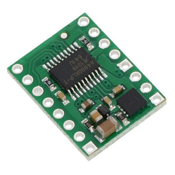


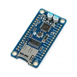


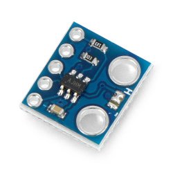


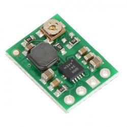

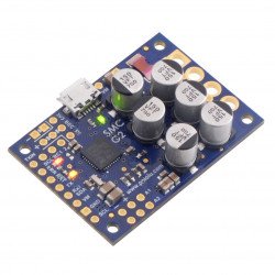


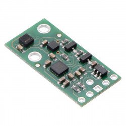

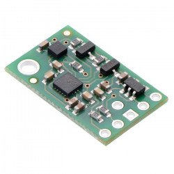


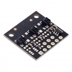


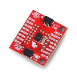


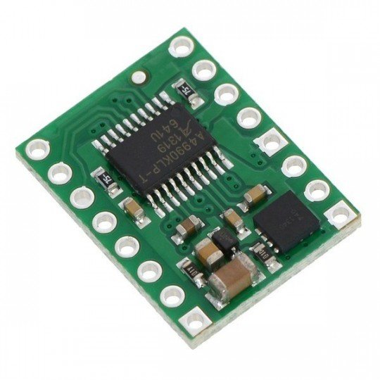
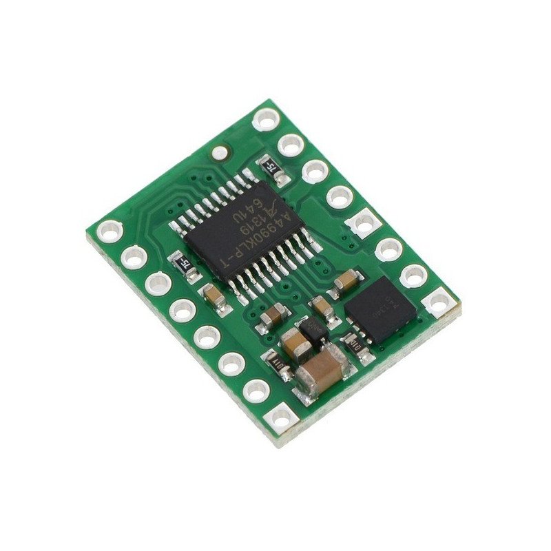


Polol module with a two-channel direct current motor controller. It works with voltages of 6 - 32 V, maximum continuous current per channel is 0.7 A.
 Product specification: Polol A4990 - dual channel 32V / 0.7A motor controller
Details in thedocumentation andin the diagram.
The A990 module byAllegrois a two-channel DC motor controller that can supply up to 0.7 A continuous current per channel with a supply voltage from 6 to 32 V. The system is dedicated for motors consuming small current at relatively high supply voltage. Apart from the controller, the board contains a protection system against reverse connection of the supply voltage polarity.
To control a single DC motor with similar parameters, we recommendthe DRV8801 controller. For motors with lower supply voltage, we recommend the double DRV8833, DRV8835 orTB6612controller.
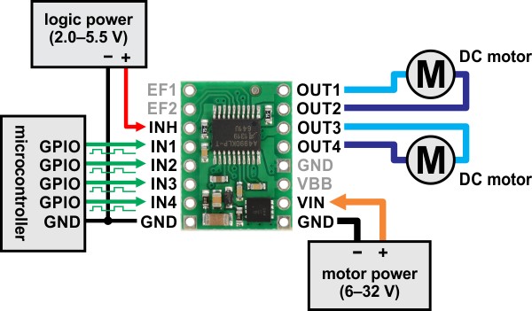
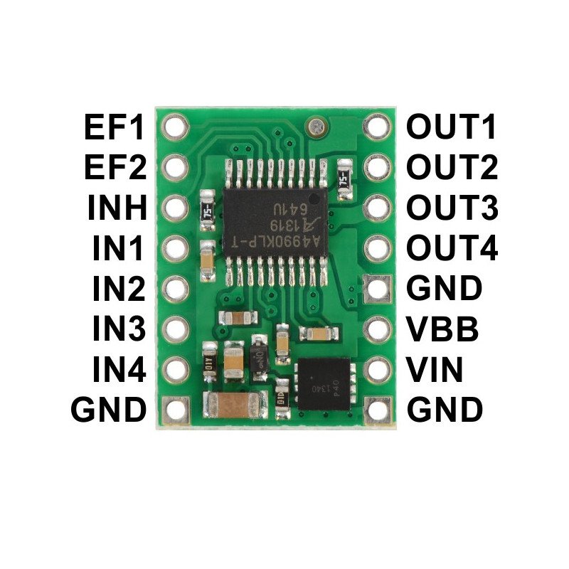
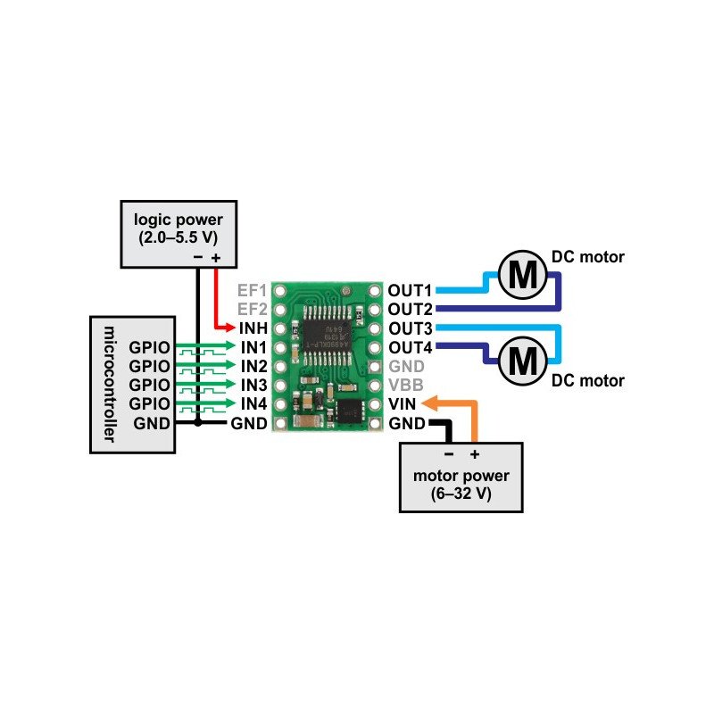
The figure shows the minimum connection of the controller.
For ease of use, all control leads are located on one side of the board. In a typical application, it is necessary to connect motor power supply and connect the logical one, i.e. voltage from the range of 2 - 5.5 V to the INH output. INH is the logical input, switching the A4990 into the sleep state after stating the low state (by default).
Each OUTx output is controlled by INx inputs. Note that the IN2 and IN4 inputs have inverted logic. Each of the inputs is disabled by default so that the motors will remain idle when connected. The truth table and more details can be found in thedriverdocumentation.
EF1 and EF2 fault flags, indicate low state of the controller's malfunction. These are open drain outputs, which means that they are not connected by default. In order to set their state it is necessary to connect external pull-up resistors or switch on those built in the microcontroller.
| Pin |
Status default |
Description |
| VIN | Power supply for 6 - 32 V motors. | |
| VBB | A voltage output that gives access to the motor start up after the reverse polarity connection protection system. It can be used to power up other components. | |
| GND | The weight of the system. Note that the mass of the engines must be connected to the mass of the control system. | |
| OUT1 | Output for engine A + | |
| OUT2 | Output for engine A - | |
| OUT3 | Output for motor B + | |
| OUT4 | Output for engine B - | |
| IN1 | LOW | Control input for OUT1. PWM signal can be connected here. |
| IN2 | HIGH | Inverted control input for OUT2. The PWM signal can be connected here. |
| IN3 | LOW | Control input for OUT3. Connect the PWM signal here. |
| IN4 | HIGH | Inverted control input for OUT4. The PWM signal can be connected here. |
| INH | LOW | Logical input, switching the system to sleep mode. Activated in a low state. |
| EF1 | No | Flag of error 1 - the output goes to a low state as a result of an error, otherwise it remains unconnected. |
| EF2 | No | Flag of error 2 - the output goes to a low state as a result of an error, otherwise it remains unconnected. |
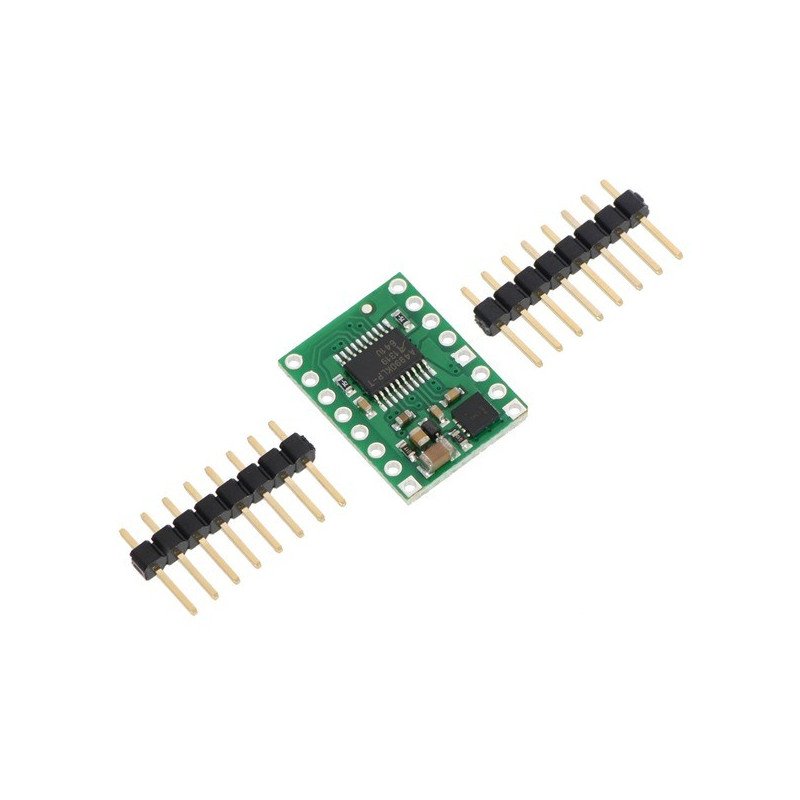
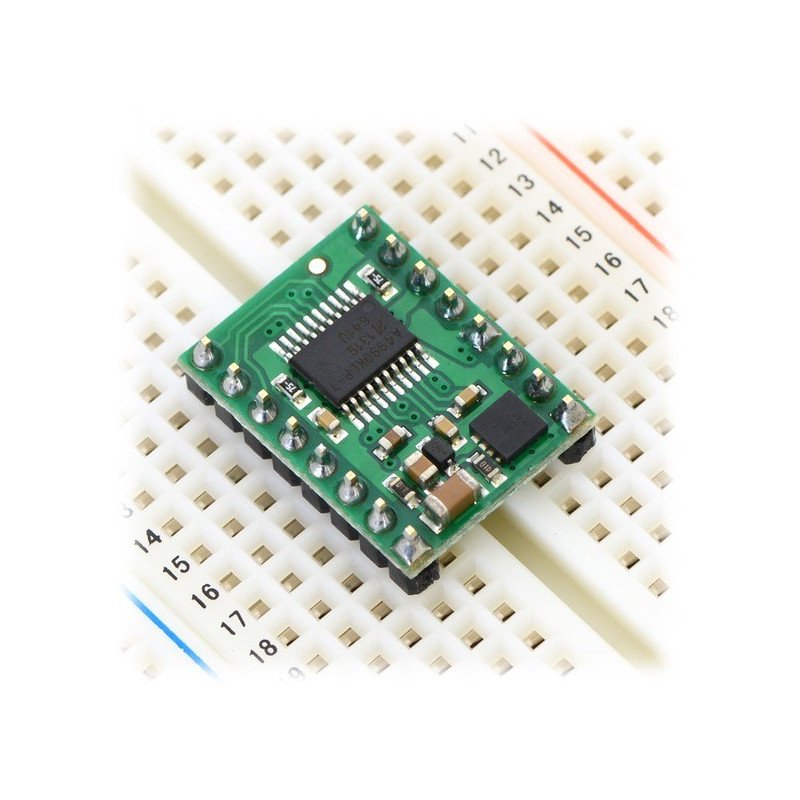
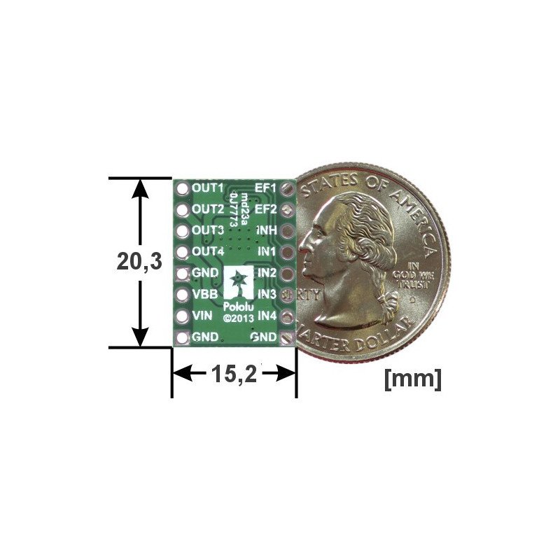
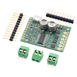
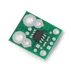
The plate is a rectangle measuring 20.3 x 15.2 mm. Outputs are holes (2.54 mm raster) for soldering populargoldpin connectors (included), which allow the sensor to be connected by wires ordirectly connectedto the contact plate.
The controller can actively limit the flow of current through a fixed frequency PWM signal. The board has 0.075 Ω resistors, which limit the maximum current to about 0.9 A per channel.
In the non-ideal real world, there are limits to the loss of energy. Due to the small area of heat transfer, the temperature of the system increases even with current flow below 0.9 A. Tests by Polol show that at room temperature the system is able to deliver 0.9 A current for about 20 seconds, after which the protection against too high a temperature is activated. The 0.7 A did not trigger the above mentioned protection. The actual current consumption will therefore depend on the cooling application and the conditions in which the controller operates.
Useful links |
| Voltage to | 6.0 V |
| Voltage from | 32.0 V |
| Current | 0.7 A |
| Channels | 2 |
| Package width | 0 cm |
| Package weight | 0.003 kg |
Be the first to ask a question about this product!