


- Reduced price

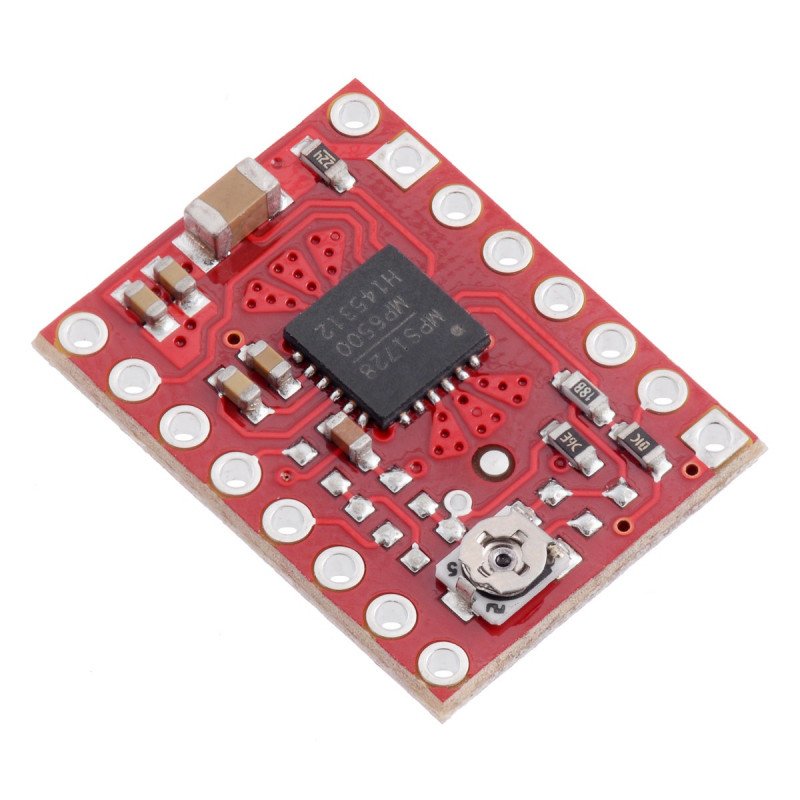


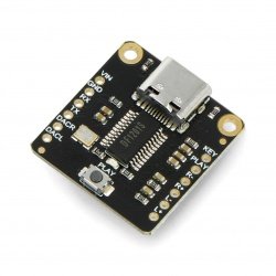
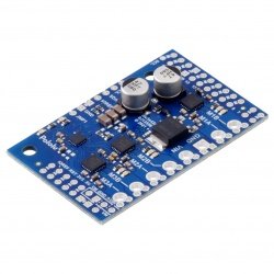
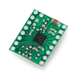
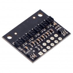
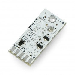
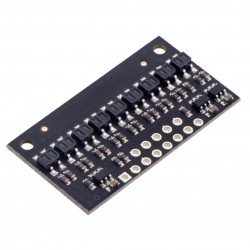
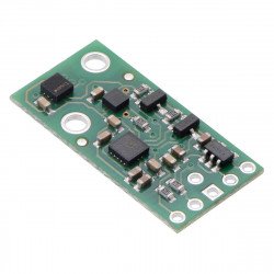
Stepper motor driver based on MP6500 chip. Powered by a voltage range of 4.5 - 35 V, with a maximum current consumption of 2.5 A per coil. Maximum resolution: 1/8 step. The module allows up to 1.8 A of current to flow without a heat sink. The current is controlled by a potentiometer.
|
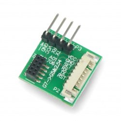
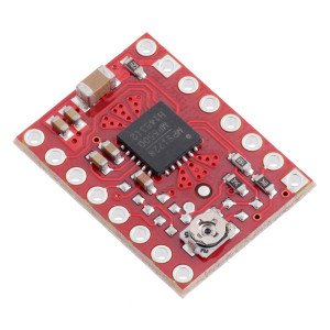
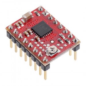
The module does not have soldered goldpin connectors. We also offer a version with soldered connectors. |
The MP6500 stepper motor driver allows you to control a stepper motor with a device that can generate logic states, e.g. Arduino, STM32Discovoery, Raspberry Pi or any other microcontroller. The Pololu module is very easy to use. In order to rotate the motor by one step, you need to send a high state (logic one) to the STEP pin, the next sequence of zero and one will move the motor by the next step and so on. The selection of the direction is done by giving the appropriate state to the DIR pin (e.g. low state - clockwise rotation, high state - anticlockwise rotation). The controller also has the ability to select the resolution of motor operation.
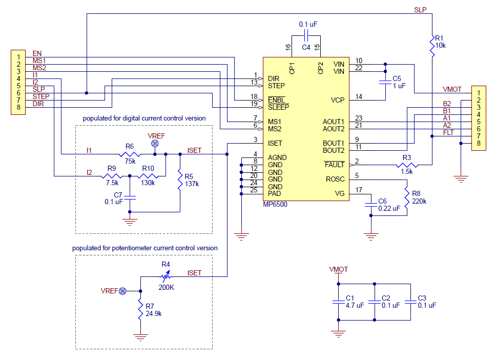
To control a bipolar stepper motor connect the system according to the diagram below. In case of controlling a unipolar motor, refer to the manual. If the nominal motor voltage is lower than required driver supply (4.5V), set the current limit manually with a potentiometer.

The figure shows the minimum connection of the controller. Between the motor power supply pin and ground there should be placed the resistor of value +/- 100 uF
Avoltage in the range of 2.5 V to 5 V is required to supply the logic part of the module, which should be connected to the Sleeppin.The motor supply voltage from 4.5 V to 35 V is applied tothe VMOTpin. The circuit can be used to control motors with a nominal voltage lower than the required 4.5 V. For this purpose, the maximum current consumption must be limited so as not to exceed the allowable motor current. For example, for a motor with a resistance of 5 Ω per coil and a current consumption of 1 A, the nominal supply voltage is 5 V. When supplied with 12 V, the current should be limited so that it does not exceed 1 A.
|
Caution! Connecting and disconnecting the motor while the controller is on can damage the system. |
The step size is selected using MS1, MS2 inputs. Possible settings are shown in the table below. The MS1 and MS2 inputs have an internal pull-down resistor (500 kΩ).
| MS1 | MS2 | Resolution |
| low | low | Full step |
| high | low | 1/2 step |
| low | high | 1/4 step |
| high | high | 1/8 step |
One pulse on the STEP pin causes one step of the motor in the direction selected by giving the corresponding logic state to the DIR pin. If the motor is to spin in one direction only, the DIR pin can be left disconnected.
The chip has two different inputs to control the power supply: SLEEP and ENBL their description can be found in the documentation. Note that the controller pulls both of these pins through internal 500 kΩ pull-down resistors. The default SLEEP state prevents the motor from running, a high state must be applied to it (it can be connected directly to a 2.5 to 5 V logic supply or it can be controlled by connecting to a digital MCU output). The default state of ENBL is controller on, it can be disconnected.
The FAULT output turns off when the F and H bridges are disabled due to current protection, overvoltage protection, thermal shutdown, or voltage dropout protection. It connects to the SLEEP pin via a 10 kΩ resistor, which functions similarly to FAULT. When SLEEP has a high state, it is not necessary to connect FAULT.
|
Note! As a result of connecting SLEEP and FAULT and when a fault occurs, the voltage on the SLEEP pin can drop below 2.1 V if it is not amplified enough. It is recommended to use resistor min. 4.7 kΩ with this pin or connect SLEEP directly to VCC. |
The circuit can be used to control motors with a nominal voltage lower than the required 4.5 V. To dothis , limit the maximum current draw using a potentiometer so that the motor current is not exceeded. For example, for a motor with a resistance of 5 Ω per coil and a current consumption of 1 A, the nominal supply voltage is 5 V. When supplied with 12 V, the current must be limited so that it does not exceed 1 A.
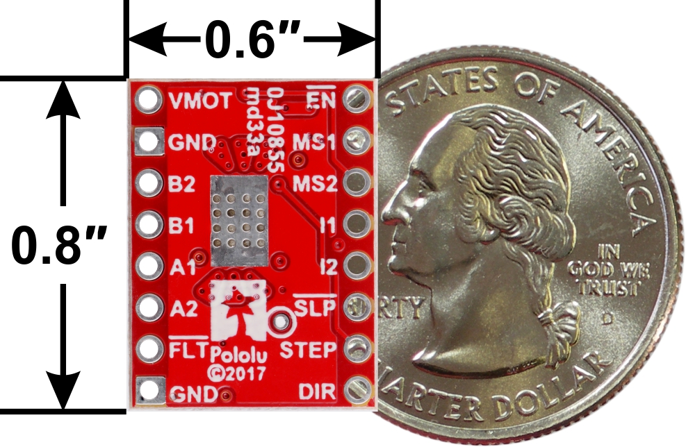
The MP6500 module allows for active current limiting using a potentiometer. One way of limiting is to set the controller to full step mode and measure the current flowing through one coil without providing a signal to the STEP input. The measured current is 70% of the set limit (both coils are always on and limited to 70% in full step mode). Another way is to measure the voltage at the VREF pinout (marked with a circle on the PCB) and calculate the current limit (the measurement resistors are 0.05Ω). More details in MP6500 chip documentation.
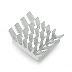
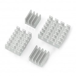
The board is designed to dissipate heat at a current consumption of about 1.8 A per coil. If the current will be much higher, you should use an external heat sink for which you can use thermally conductive glue.
The circuit contains the necessary passive components for proper operation of the controller. The circuit diagram is shown in the figure below.
Useful links |
| Package width | 8 cm |
| Package height | 0.3 cm |
| Package depth | 8 cm |
| Package weight | 0.003 kg |
Be the first to ask a question about this product!


