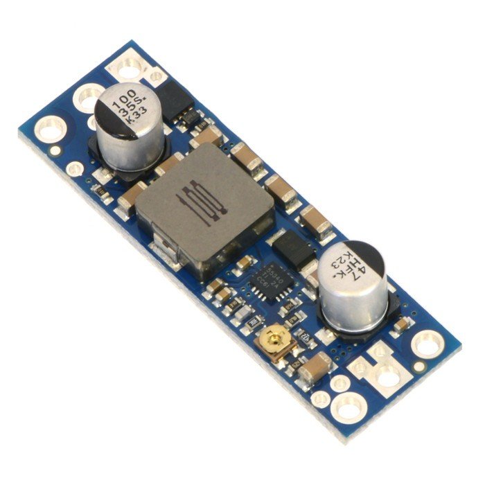


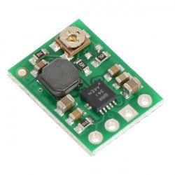

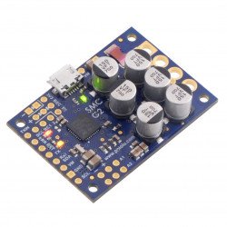


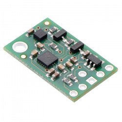


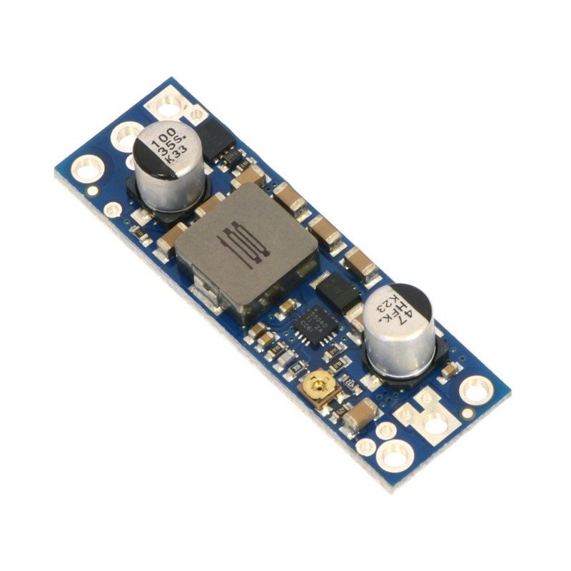


Upgrade inverter with adjustable 4 - 12 V output voltage. The permissible input voltage range is 2.9 - 12 V and the maximum input current that the system can process is 5 A.
A controller that increases the input voltage from 2.9 V to 12 V to an output value selected by a potentiometer from 4 V to 12 V, assuming that the output voltage cannot be higher than the input voltage. The system is able to process a maximum input current of 5 A and its efficiency is 80 - 95 %. Output current is a function of input voltage, output voltage and inverter efficiency. It is usually the value around the input current, i.e. 5 A. Details can be found in the diagrams below.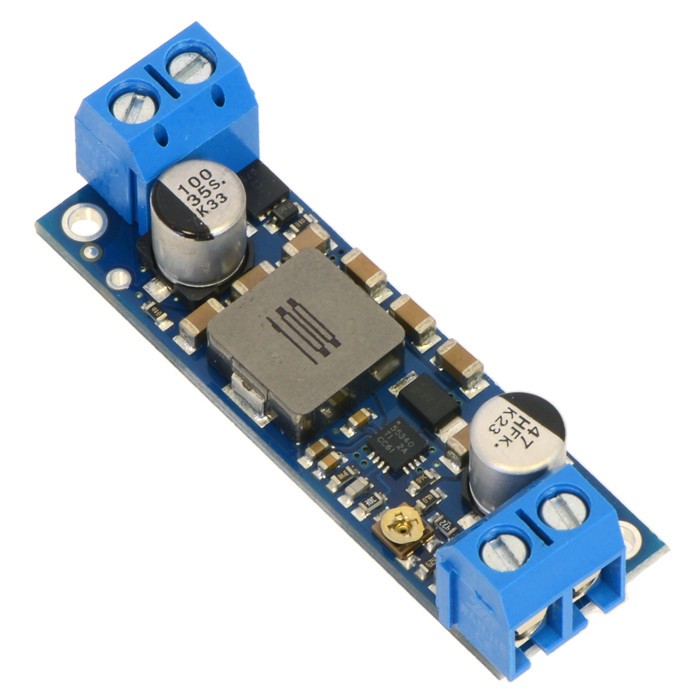
The U3V50x family offers two versions of inverters with adjustable output voltage:U3V50ALV (4 - 12 V), U3V50AHV(9 - 30 V).Constant voltage versions are also available: 5 V, 6 V, 9 V, 12 V and24 V. All versions of the U3V50x are similar to each other, for easy identification, there is a blank space on the back where you can place your own marker.
 Inverter specification
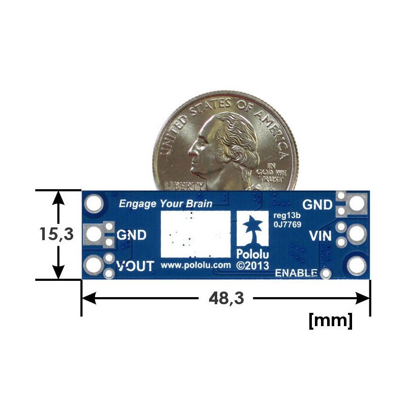
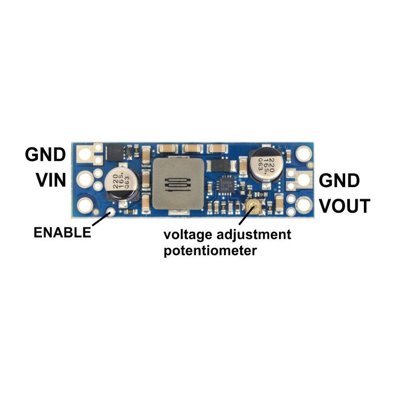
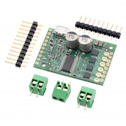
The module has four outputs:
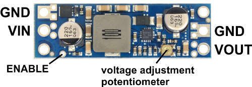
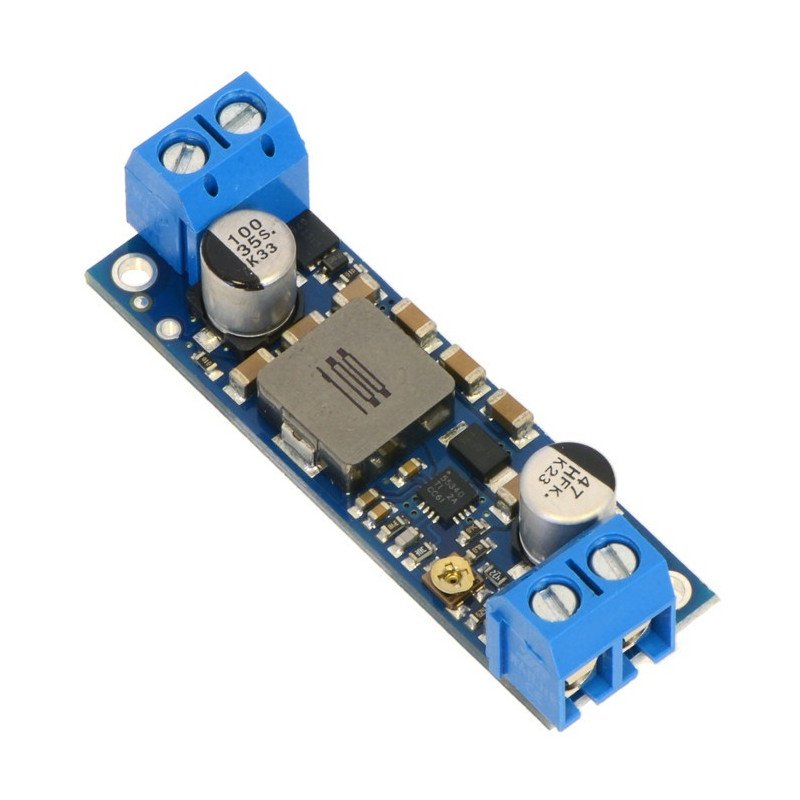
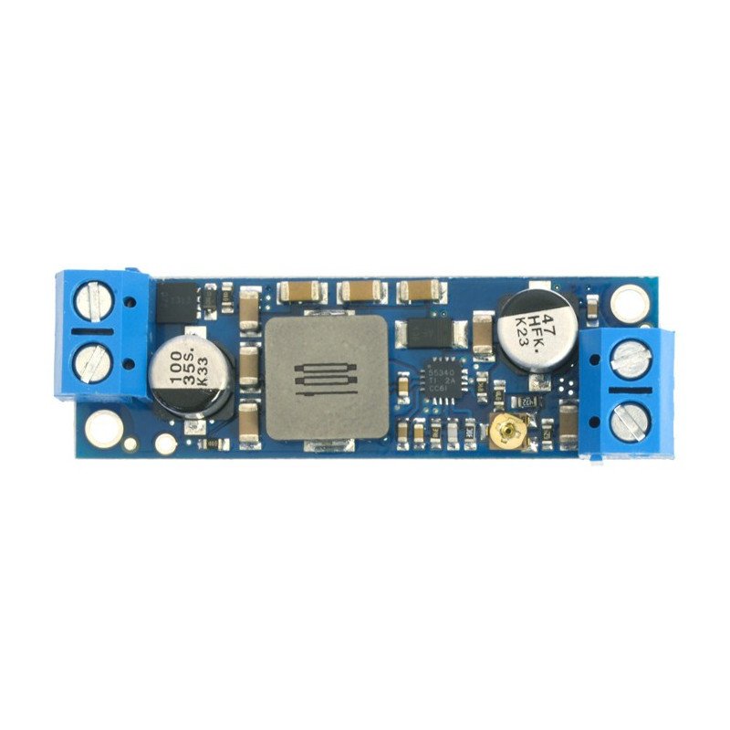
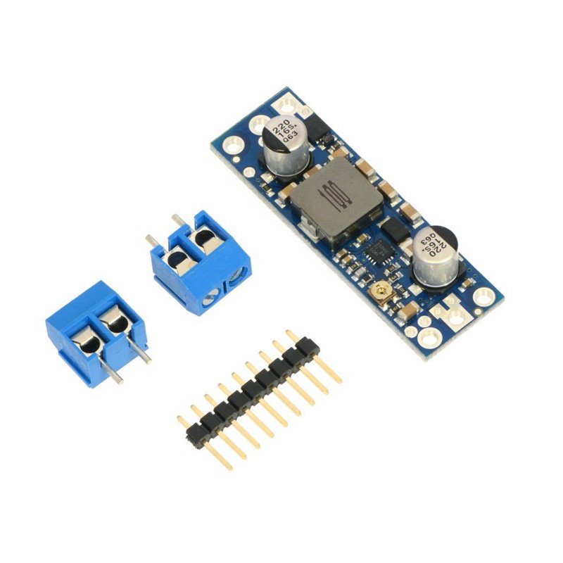
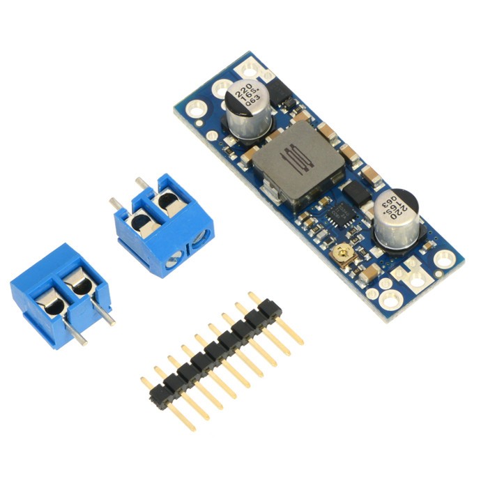
The connectors are properly signed on the board. The output grid is 5 mm for ARK connectors and 2.54 mm for connectorsgoldpinwhich allow the module to be mounted incontact plateorconnectionby means ofcables.

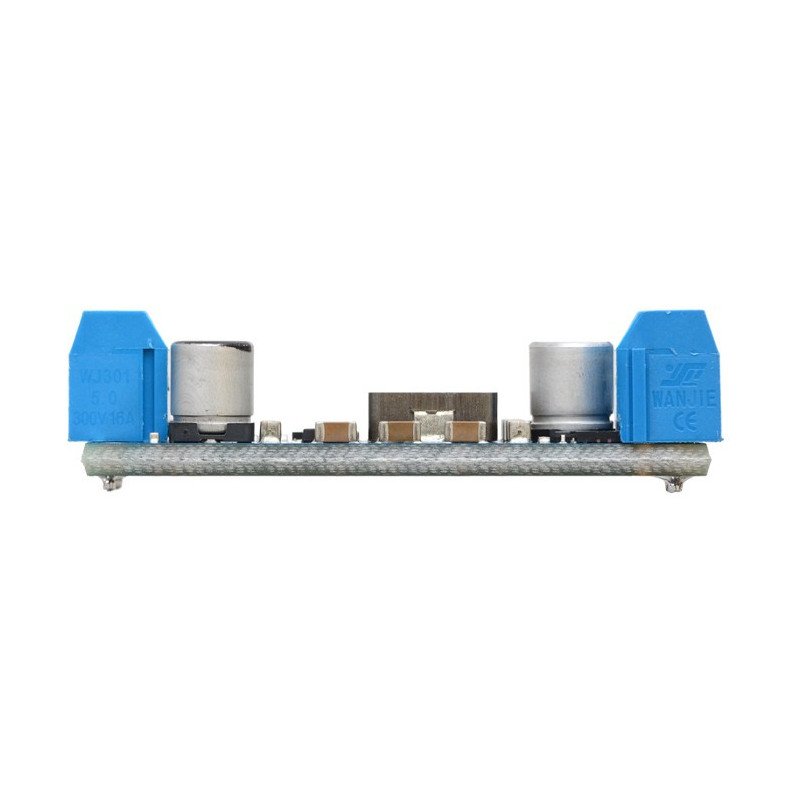
Soldering connectors for self-soldering are included. You can choose popular goldpins or ARK high-current terminals. Thanks to the thicker PCB layer the terminals do not stick out of the circuit.
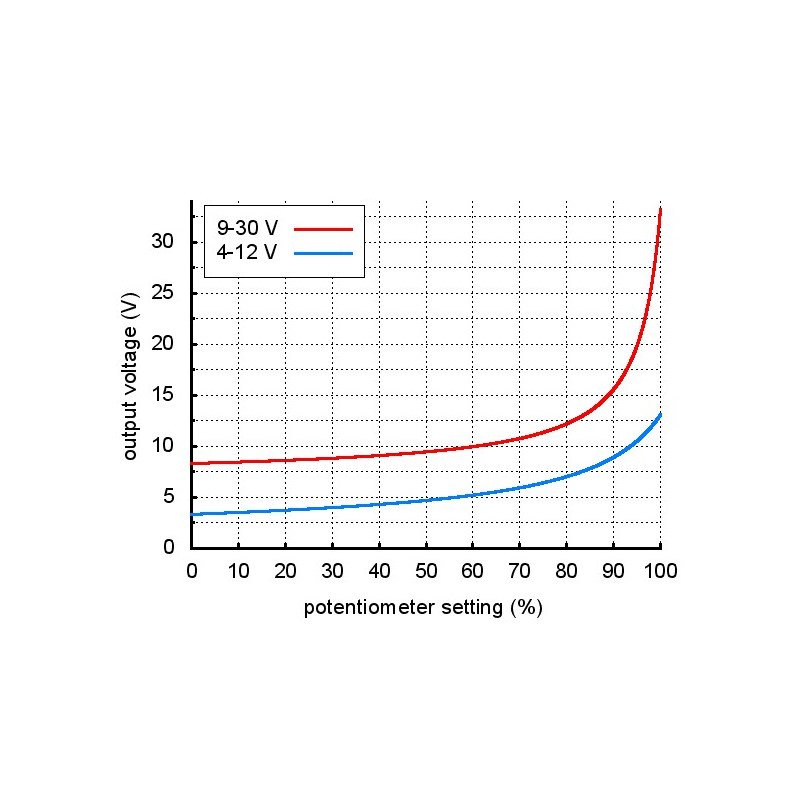
The voltage is set using a potentiometer. A multimeter with a small resistive load (e.g. resistor 10 - 100 kΩ) can be used to select a suitable value. Turning the potentiometer to the right increases the output voltage. Touching the potentiometer or the system itself with your hand or finger can affect the output voltage - so we recommend to be careful when doing so.

Fig.: Selection of the output voltage.
|
Attention! Please note that the input voltage must not exceed the output value. The potentiometer has no physical blockage, therefore the output voltage should always be set by measuring its value so as not to exceed the maximum value. |
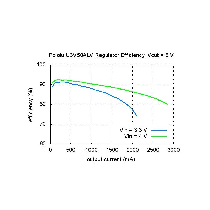
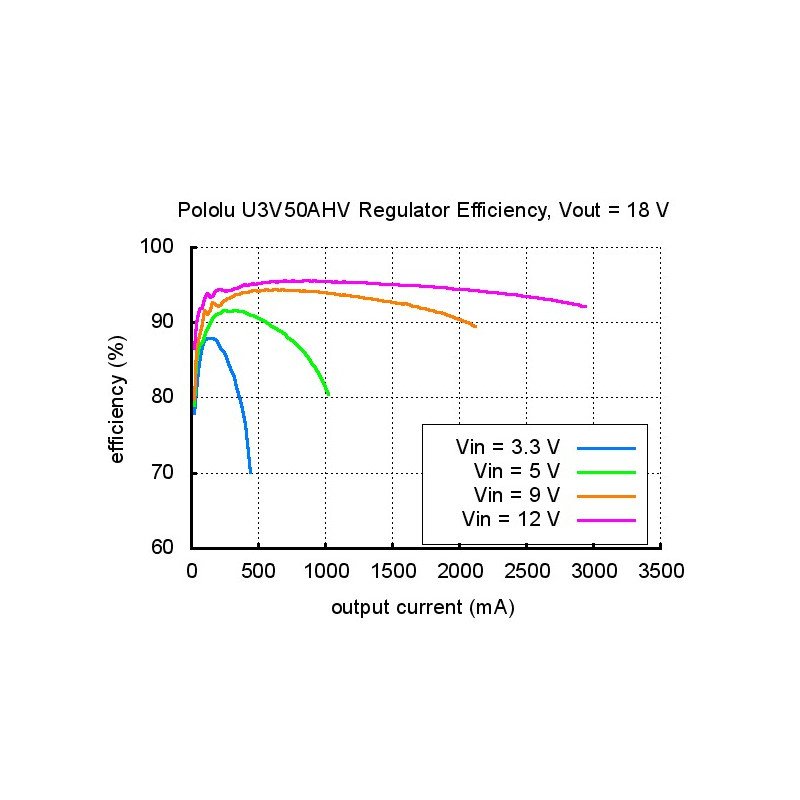
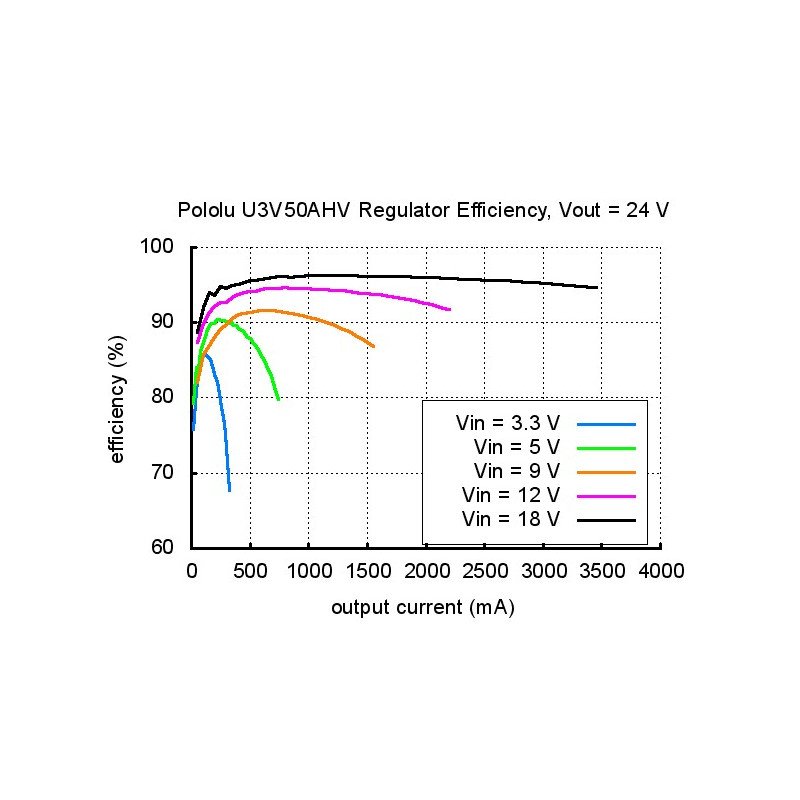
The efficiency of the inverter depends on the input voltage and the selected output voltage. On average, it ranges from 80 % to 95 %. The output current is a function of the input voltage, output voltage and inverter efficiency. It is usually the value around the input current, i.e. 5 A.

Figure: System efficiency at 5V output voltage.

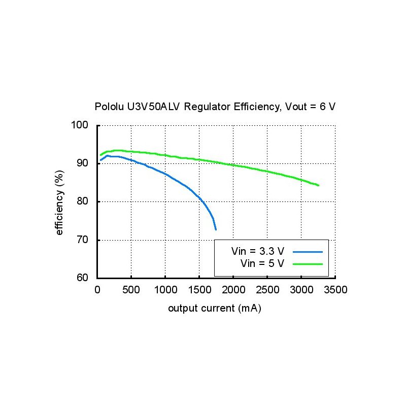
Fig.: Efficiency of the system at 6V output voltage.

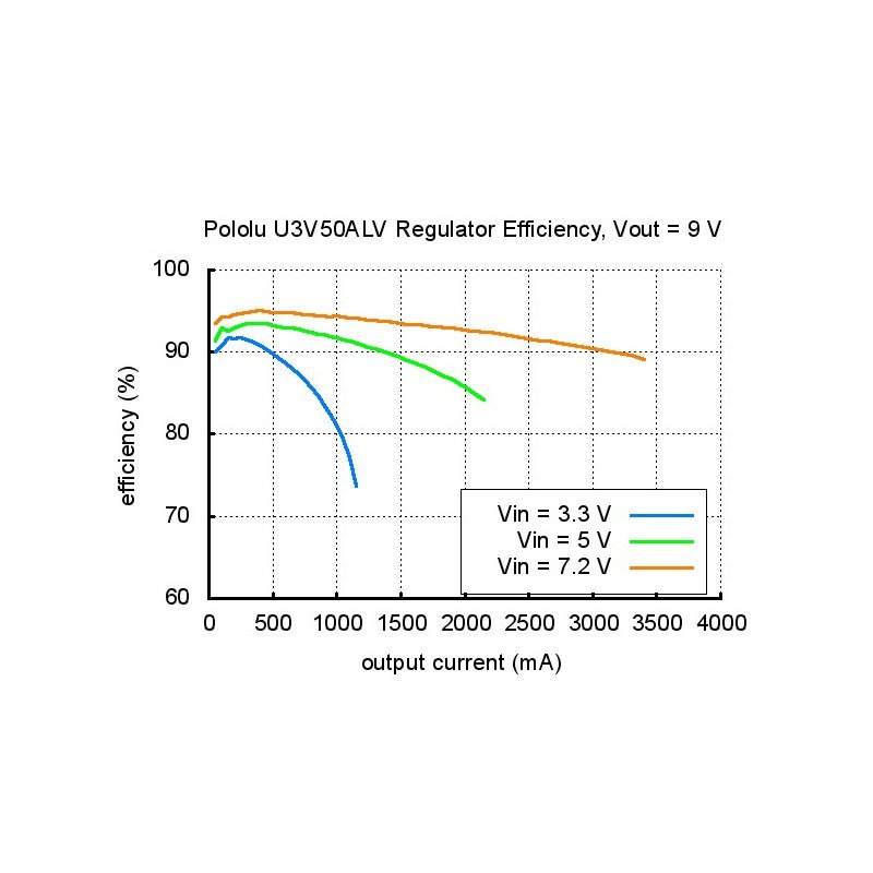
Fig.: Efficiency of the system at 9 V output voltage.

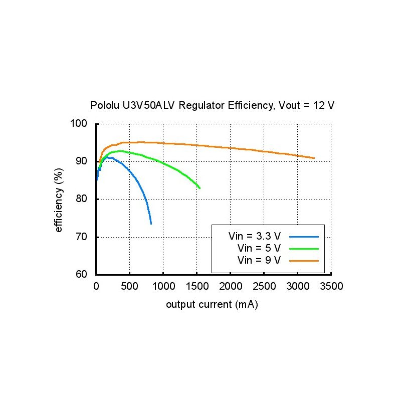
Fig.: Efficiency of the system at the output voltage of 12 V.

Fig.: Efficiency of the system at 18 V output voltage.

Fig.: Efficiency of the system at 24 V output voltage.
To sum up, the maximum output current is proportional to the ratio of input voltage and output voltage. Additionally, its value may depend on external factors, e.g. temperature or air flow or the heatsink used. If the input current exceeds 5 A, The output voltage will start to fall below the set value.
Useful links |
| Length | 48 mm |
| Width | 15 mm |
| Height | 10 mm |
| Voltage to | 2.9 V |
| Voltage from | 12.0 V |
| Voltage output from | 4.0 V |
| Output voltage to | 12.0 V |
| Current | 5 A |
| Stabilizer - Type2 | switching |
| Stabilizer - Type | step-up |
| Package width | 8 cm |
| Package height | 1 cm |
| Package depth | 10 cm |
| Package weight | 0.013 kg |
Be the first to ask a question about this product!