


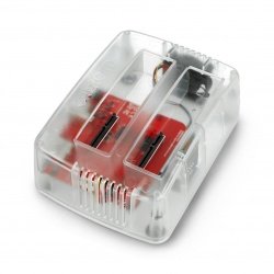


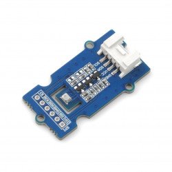


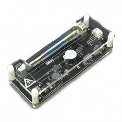


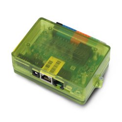
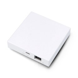


The analog-to-digital converter is a popular accessory for Raspberry Pi. This 4-channel converter is based on the ADS1115 from Texas Instrument, which is a precision, energy-saving 16-bit ADC chip. The sensor fits the size of the Raspberry Pi Zero and has an integrated analogue Grove connector so you can also use the analogue Grove modules with it.
|
Buy it now |
Properties
- LOW power consumption:
- Continuous mode: only 150μA
- Single-shot mode: automatic shutdown
- Wide range of supply voltage
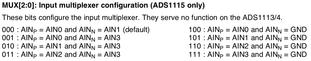
- Input multiplexer (MUX), which provides two differential inputs or four single inputs
- Programmable comparator
- Internal low-drift reference voltage
- Internal oscillator
- Internal PGA
- Programmable data rate: 8SPS is 860SPS
- I2C compatible serial interface
Specifications
| Feature | Value |
|---|---|
| Supply voltage | 3.3 V / 5 V |
| Analog input intensity | 100mA (temporary) 10mA (continuous) |
| Storage temperature | -60~150℃ |
| Maximum joint temperature | 150℃ |
| Interface | I2C |
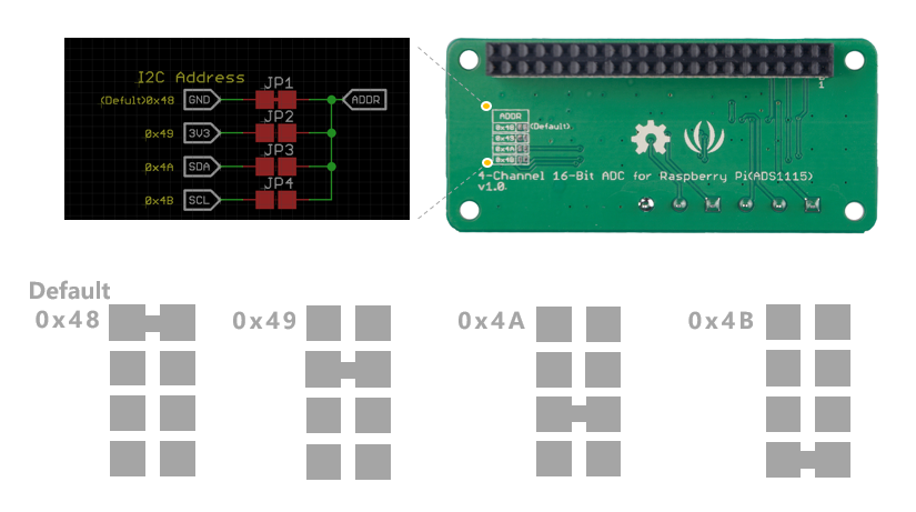
| I2C address | 0x48(default) 0x49~0x4B (configurable) |
| Dimensions | 65 x 30 x 20 mm |
| Weight | 36.5 g |
| Packaging dimensions | 140 x 78 x 27 mm |
| Gross weight | 37 g |
This grove has 4 possible I2C addresses, from 0x48 to 0x4B. The default I2C is 0x48. You can change the I2C address by soldering.
|
Note If the SDA (corresponding 0x4A address) is used as a device address, keep the SDA low on the SDA line for at least 100 ns after switching to a low SCL state to ensure that the device decodes the address correctly during I2C communication. |
Typical applications
- Portable instrumentation
- Consumer goods
- Battery monitoring
- Temperature measurement
- Industrial automation and process control
Equipment overview
Exit timetable
How to get started
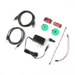
Equipment
Required materials
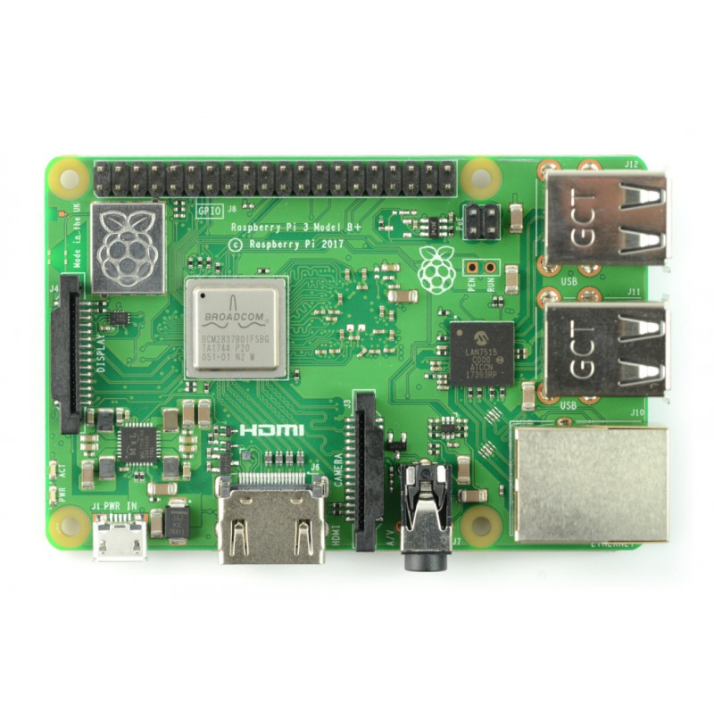
| Raspberry Pi |
Analogue-to-digital converter for Raspberry Pi 4-channel 16-bit (ADS1115) |
|---|---|
 |
|
Software
In this section you will learn how to install the driver and how to enable the I2C bus.
Enable I2C because I2C is disabled by default, you must configure it manually.
- Step 1: Connect power to Raspberry Pi.
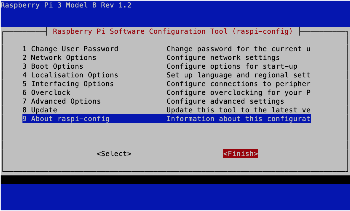
- Step 2. open the raspi-config by entering the following command in the terminal.
sudo raspi-config
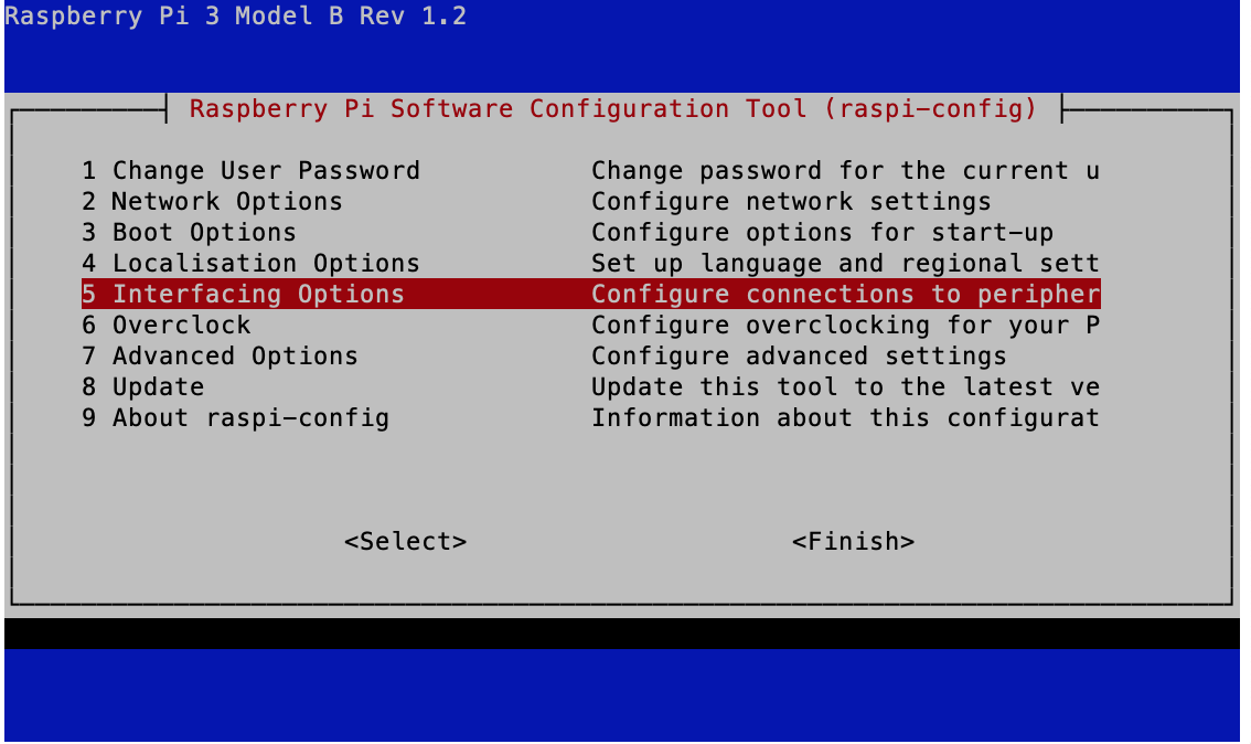
- Step 3: Go down to "5 interfacing options" and press "enter" to select.
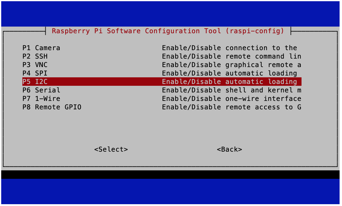
- Step 4. go down to "P5 I2C" and press "enter" to select.
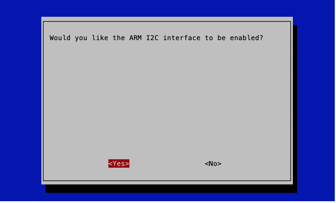
- Step 4. select "Yes" to enable.
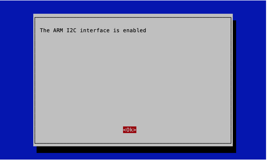
- Step 5. select "Ok".
- Step 6 Choose "Finish" to save your changes.
Installation
|
Note Follow the instructions during installation, otherwise the installation may fail or even damage the module. |
- Step 1: Connect the power supply to the Raspberry Pi.
- Step 2. Open the terminal and enter the following command.
git clone https://github.com/Seeed-Studio/pi-hats.git
cd pi-hats
sudo ./install.sh -u adc_ads1115
- Step 3: Disconnect the power from Raspberry Pi.
- Step 4: Insert the cap into the Raspberry Pi
- Step 5: Connect the power supply to Raspberry Pi.
Displaying the installation status
.../install.sh -l
|
Success If the installation was successful, you should see the following message. |
pi@raspberrypi:~/pi-hats $ ./install.sh -l
adc_ads1115 : installed
rtc_ds1307 : not installed
rtc_ds3231 : not installed
Uninstalling
Sudo ./install.sh -u
ADC operating guide
0-3 channels are differential voltage, full scale range -2.048V - +2.048V
channels 4-7 is absolute voltage AIN0-AIN3, full scale range 0 - +2.048V
Read AIN0(channel 4) voltage (unit: mV).
cat /sys/devices/platform/soc/*04000.i2c/i2c-1/1-0048/in4_input
| Entry | Channel | /...XXX |
|---|---|---|
| AIN0 | 4 | in4_input |
| AIN1 | 5 | in5_input |
| AIN2 | 6 | in6_input |
| AIN3 | 7 | in7_input |
Read all channels at once.
./ads1115.sh
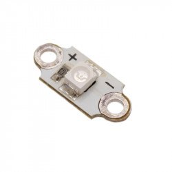
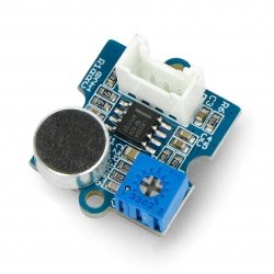
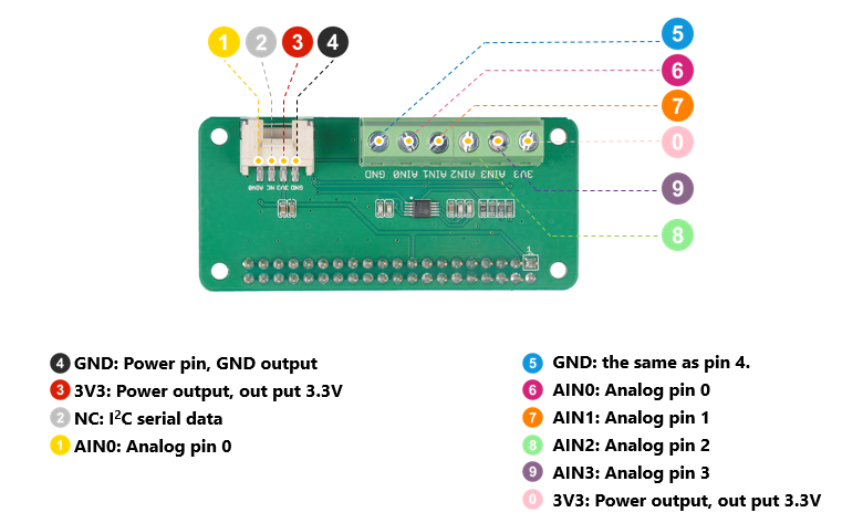
Let's use the example Grove- Sound Sensor. If you use a grove cable to connect a sound sensor with ADC overlay as shown below, it means you are using A0 (fourth channel). Now run the ++ command. / Ads1115.s ++ inside the terminal, you will see the following message if the sound sensor data is read.
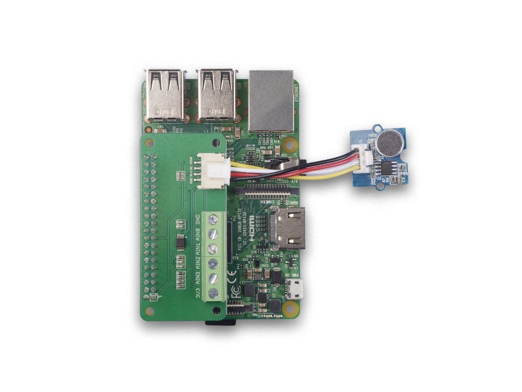
pi@raspberrypi:~/pi-hats $ ./ads1115.sh
3f804000.i2c
four channels' value are :
1024
,
285
,
285
,
285
four channels' value are :
796
,
285
,
285
,
285
four channels' value are :
304
,
286
,
283
,
283
four channels' value are :
366
,
284
,
284
,
283
^Pippercuttering: ~/pi-hats $
|
Success You will notice that channels 5, 6, 7 are more or less constant, while channel 4 reads only some data. |
Links
-
[Zip] 4-channel16-bit A/D converter for Raspberry Pi (ADS1115) Eagle files
-
[Zip] 4-channel16-bit analog-to-digital converter for Raspberry Pi (ADS1115) Software library
-
[PDF]Technical DataSheetADS1115