


Grove - Starter Kit v3 - starter Kit
Grove is a platform e-mail, which is used for convenient and fast prototyping. Allows Assembly of multiple projects without the need for soldering or using contact plates. Simply plug the Grove modules into the Grove shieldu and use the sample code. Grove starter kit consists of several sensors, in particular of sound, light, movement and touch. This is the first set of Grove is available in Polish language version. Because of this now you can start to experiment with new projects.
Introduction
What is Grove?
Grove is a ready to use set of elements. The method of Assembly is reminiscent of LEGO, approach, to build of cubes, was applied on the basis of electronics. Compared with the traditional teaching methods of Assembly of electronics, Grove greatly facilitates and shortens this process. The Grove system consists of a base module (Base Shield) and the various other modules with connectors that are compatible with this system.
The base module allows easy low I / o microprocessor modules of the Grove. Each module has one function, as, for example, a simple button or a more complex heart rate sensor. Attached to each clear documentation and sample code to facilitate the beginning of work.
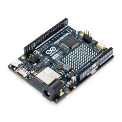
Meet Arduino
If you are new to Arduino, check out the instructions below:
Download link of Sketch of the Grove Starter Kit is here.
Now you are ready to begin your adventure with the Grove!
Parts catalog
-
1*Grove – base Shield Base module
-
1*Grove – LCD RGB backlight
-
1*Grove – smart relay
-
1*Grove – Buzzer
-
1*Grove – sound Sensor
-
1*Grove – touch Sensor
-
1*Grove – angle Sensor
-
1*Grove – temperature Sensor
-
1*Grove – LED
-
1*Grove – light Sensor
-
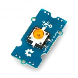
1*Grove – Button
-
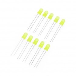
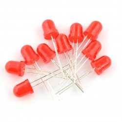
1*DIP LED blue-blue
-
1*DIP LED green-green
-
1*DIP LED red-red
-
1*Grove – Mini servo
-
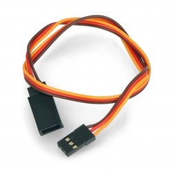
10*Grove Cable
-
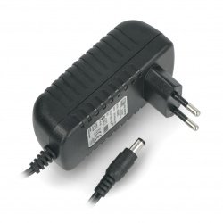
1*Adaptor 9V-Barrel Jack
-
1*manual for the starter kit Grove
-
1*Green plastic box
Detailed information
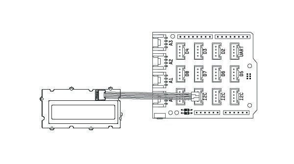
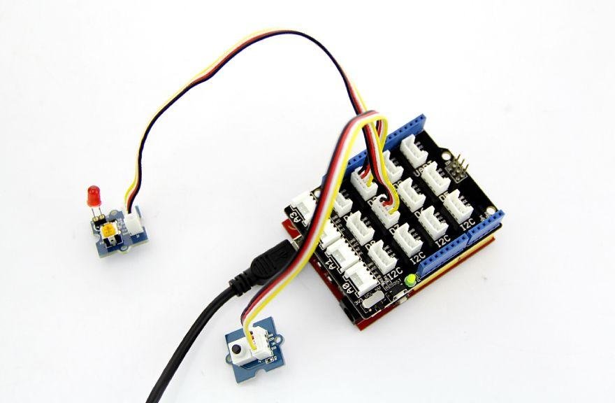
Grove – basic Module (Base Shield)
Let's start with the basic tiles. Base Shield is the new version of Electronic Brick Shield. It is compatible with Seeeduino v3.0 (168p and 328p), and Arduino UNO Duemilanove I. Grove Has 16 ports divided into four different functional zones: analogue(4) digital(7), I2C(4) UART(1).
-
Connectors digital
As you can see in the picture above, the module has seven ports digital labeled D2-D8. Each of them supports several digital pins (2/3 8/9...) on the Arduino Uno. Connectors can be used to read digital sensors (for example, buttons) or to control drive digital or analog audio via PWM). In both cases, each port supports only two logical States: 0 or 1.
-
Connectors analog
On the left side of the Board there are four connectors for analog output. Analog sensors displays readings in the range 0 - 1023. Compared with digital sensors that only show 0 or 1, analog readings are much more accurate and precise.
-
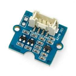
I2C connector
Under the digital ports is four ports, I2C Grove. I2C-bus Protocol at low speed, which transmits data by two lines: SCL and SDA. SCL is the clock line for synchronizing data transfer on the I2C bus; SDA data line.
Details of the use of core modules Grove Base Shield you will find at the following link: core Module - Base Shield V2.
Grove – LCD RGB
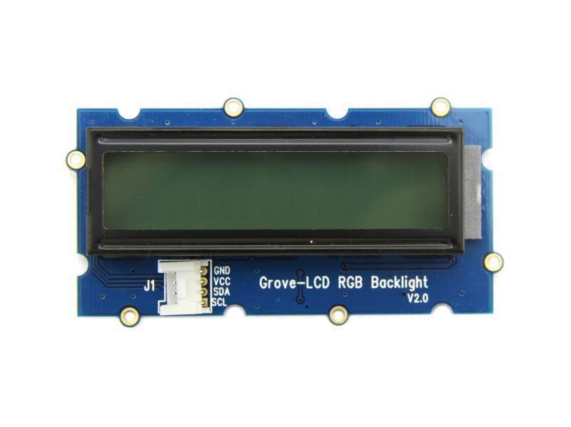
LCD RGB display allows you to display text using the characters defined by the user. With a simple interface Grove you can set the illumination color. It uses I2C to communicate with Arduino. Due to the fact that the number of pins required for data exchange and backlight control is reduced from about ten to two, leaving more I/O ports to handle other complex tasks.
Example
The following example shows how to display text on the screen and change the color of the backlight. To do this, use the path:
File -> Sketchbook -> Grove_RGB_Backlight_LCD -> HelloWorld
Tips
This LCD 16x2 screen that displays two lines of 16 characters each. This version is characterized by the support of the Russian language. The display also supports many other languages, M. . English and Japanese. You can use custom characters and define their designs. Example of creating such characters you will find here:
https://github.com/Seeed-Studio/Grove_LCD_RGB_Backlight/archive/master.zip
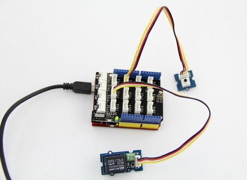
Grove – Relay
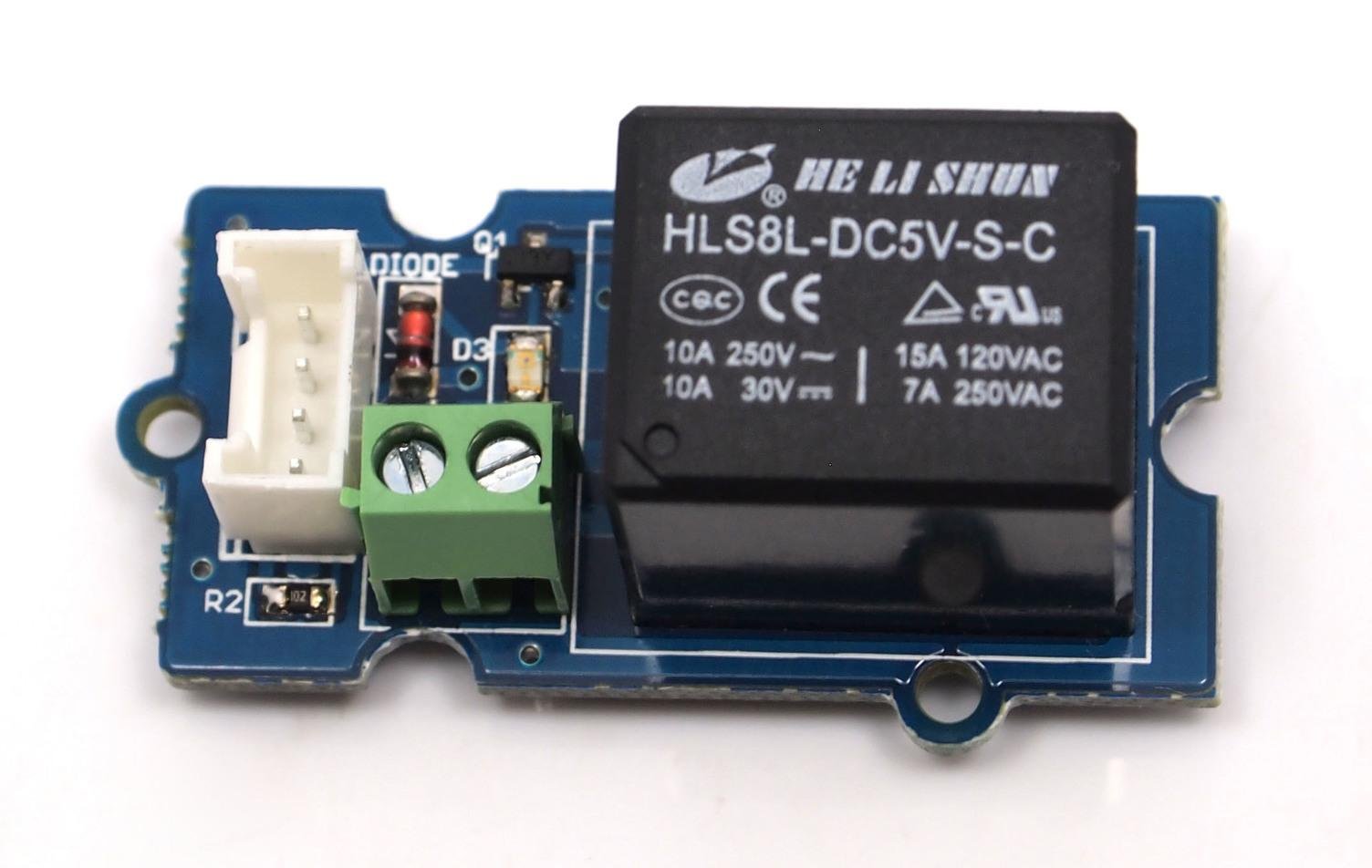
Relay is a useful tool for increasing control over Arduino. Digital signal connect to the interface and Grove relay will be able to open and close the internal circuit is connected to the connectors on the screw. Voltage can reach 220V. Do not hesitate and get yourself in really challenging projects with relay Grove!
Example
An example of how to drive relays with the button: File -> Sketchbook -> Grove_Relay.
Tips
Relay controlled controlled electronics. Its size is slightly different depending on the abilities current. The more relays (and, in principle, only by its plastic case), the more current can flow on it.
| Take special care when working with high voltages - if in doubt contact a qualified electrician for help. |
Details of the use of relay Grove you will find at the following link: Grove – Relay.
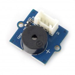
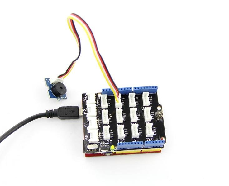
Grove – Buzzer
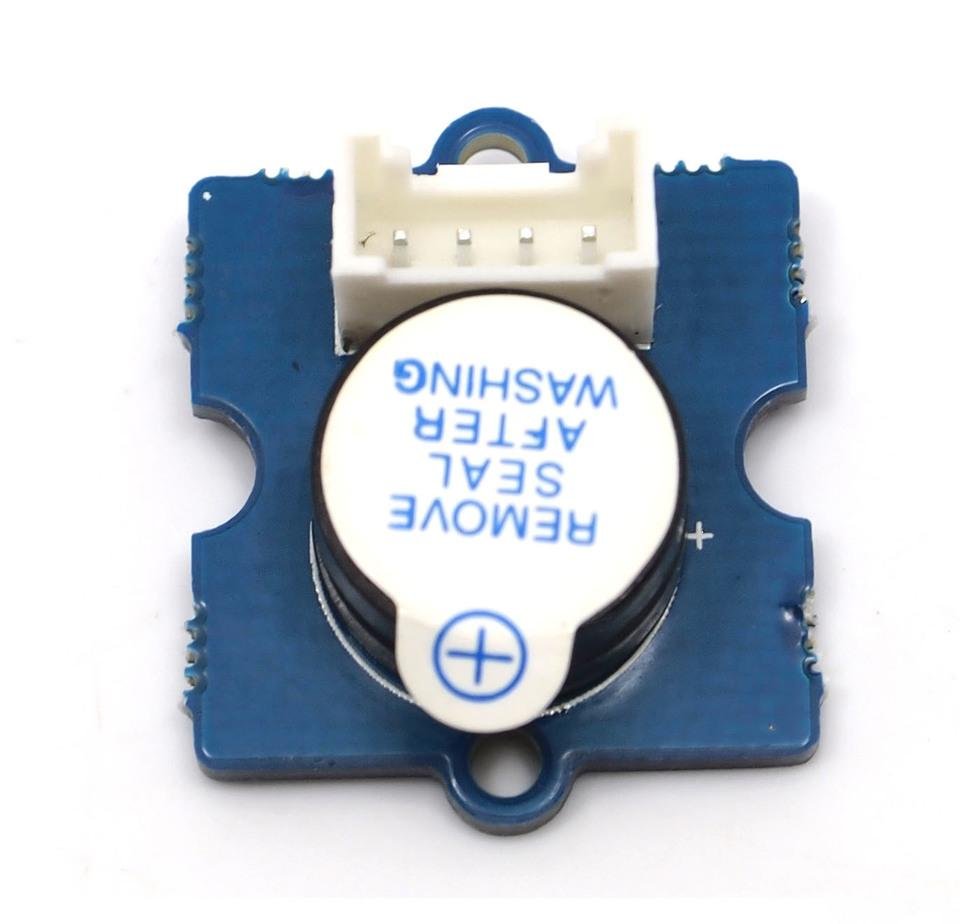
The buzzer is a simple but very effective device. This piezoelectric loudspeaker coupled with a simple control scheme that makes sounds at high state. Can also be connected to analog to generate various sound effects.
Example
You can use the code for the button Grove to get Your buzzer humming when you press the button. The buzzer is not only used for fun, can play songs! Below you will find, for example, Oomlout.com in which the buzzer game well-known children's rymowankę – “Twinkle Twinkle Little Star”.
Use the following paths to find the example: File -> Sketchbook -> Grove_Buzzer
Tips
I wonder how the buzzer? Typically, each buzzer comprises a ceramic tile. Depending on the applied voltage, the plates attract each other or recede from each other. The movement of platelets causes air vibration, and thus generates sounds. Along with the change of the frequency of vibration also varies the frequency of the sound.
Detailed information about working with the buzzer Grove you will find at the following link: Grove - Buzzer.
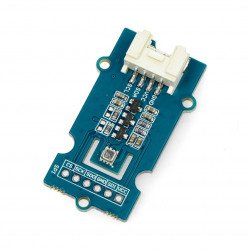
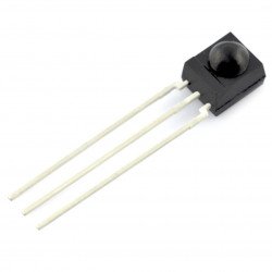
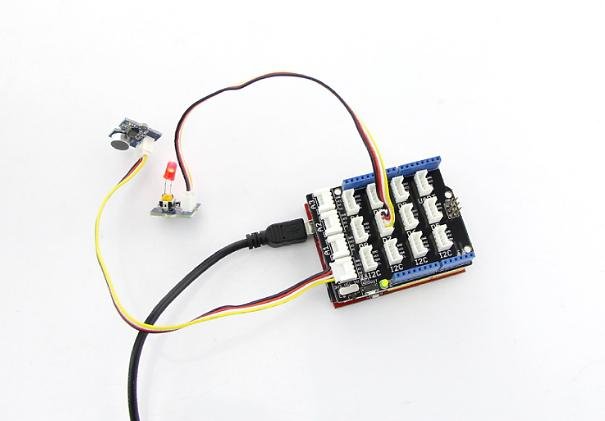
Grove – sound Sensor
The sound sensor is a simple microphone. Opera on the amplifier LM358 and microphone elektretowym. It can be used to detect the sound level of the environment.
Example
Code of the sound sensor can also be used to control LED lighting. The brightness of the light-it then depends on the intensity of the sound environment.
File -> Sketchbook -> Grove_Sound_Sensor
Tips
Electret microphone collects sound intensity at all frequencies, and in turn, a potentiometer can work as a regulator. For instance, when fully turning the potentiometer clockwise, the microphone determines everything. But when you turn it to the left will not detect anything.
Details of operation of the sound sensor Grove you will find at the following link: Grove - Sound Sensor.
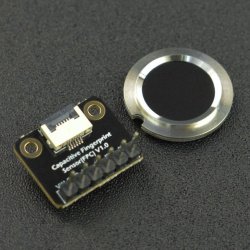
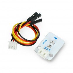
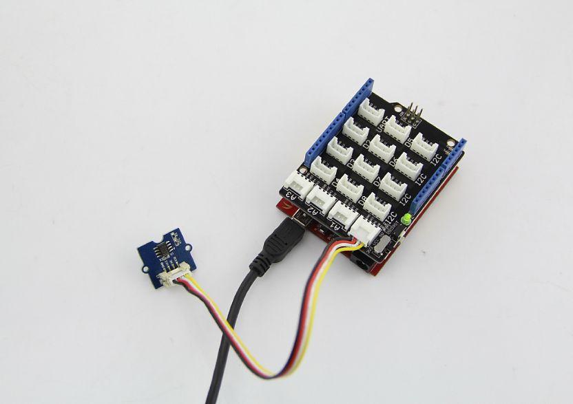
Grove – touch Sensor
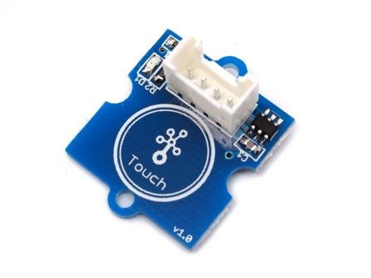
The touch sensor Grove allows you to replace the traditional touchpad button. Detects a change in capacitance when the finger is in its immediate vicinity. So no matter if your finger directly touches the pad or just in its immediate, the sensor will go high.
Example
Code for the button Grove also works with this module. For example, you can find via this path: File -> Sketchbook -> Grove_Buzzer
Tips
The sensor is an alternative to the button instant. The Grove touch sensor detects a capacitance change on the round (niepomalowanym) region at the bottom of the module. The closer to this region, give me your finger, the more there is a change in capacitance. The sensor operates correctly even if you put a sheet of paper between it and the finger.
Details of the use of the touch sensor Grove you will find at the following link: Grove - Touch Sensor.
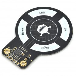
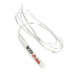
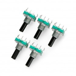
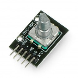
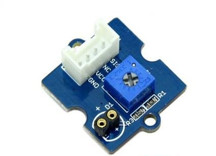
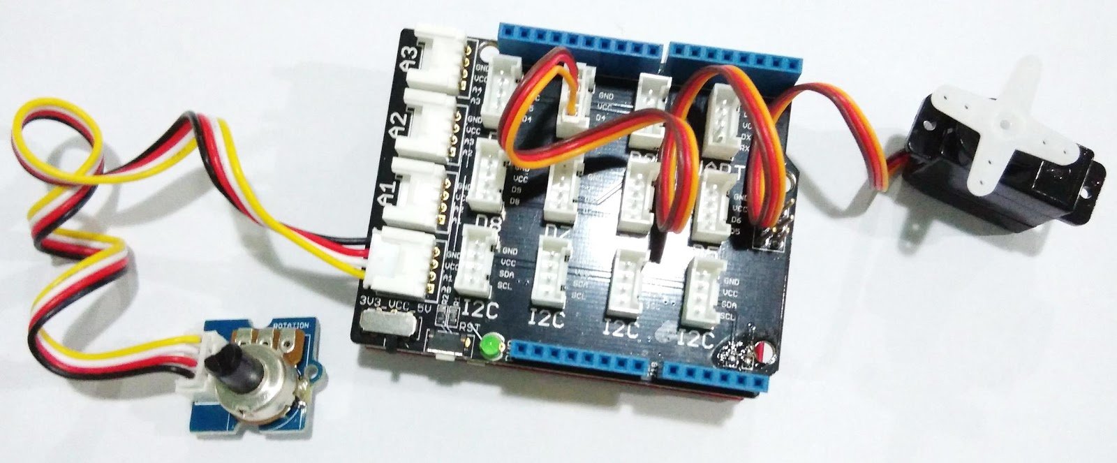
Grove – rotary linear Potentiometer
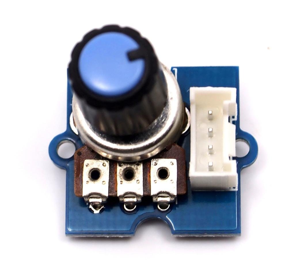
The potentiometer Grove produces analog output between 0 and VCC (3.3 or 5 VDC). The angular range is 300 degrees with a linear change value. The resistance value is 10k Ohm, which ensures a perfect value to use with Arduino.
Example
The following example shows how to read the value of the angle sensor of the moment:
File -> Sketchbook -> Grove_Rotary_Angle_Sensor

Tips
Potentiometer rotary is very similar to the rotary encoder, but they are not the same. It is, in principle, a potentiometer slide round shape. According to the analog method of dzielniku voltage used contact sliding.
Details of the use of the angle sensor time Grove you will find at the following link: Grove - Angle Sensor Now.
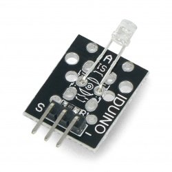
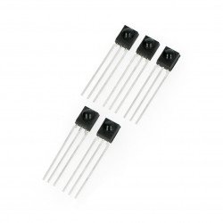
Grove – temperature Sensor
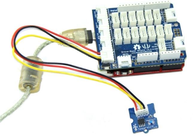
The temperature sensor Grove uses a thermistor working temperature of the environment. Our tile processes the voltage value measured via the analog connector on the temperature. Range is -40°C to 125°C.
Example
The following example shows how to handle the output of the sensor into a temperature value. Monitor serial port display data in degrees Celsius:
File -> Sketchbook -> Grove_Temperature_Sensor.
Tips
The Grove temperature sensor is used to determine the ambient temperature.
Details about using the temperature sensor Grove you will find at the following link: Grove - Temperature Sensor
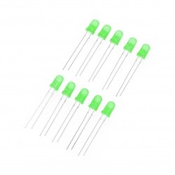
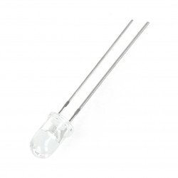
Led
The Grove led is designed for beginners of Arduino/Seeeduino to control from the digital connectors. The led can be easily attached to the surface of a box or table. The diode can be used as a lamp pilotującą the flow of current or signal.
Example
In this example, we create LED light with a flicker effect:
File -> Sketchbook -> Grove_LED
Tips
We have prepared for You three colors of LEDs. The color can be changed with connector LED Grove. The cathode is on the flat side of the diode, and the anode on the round page. So the indicator worked correctly, the anode must be connected through places with the sign ‘+’.
Details of the use of led Grove you will find at the following link: Grove - Red Led.
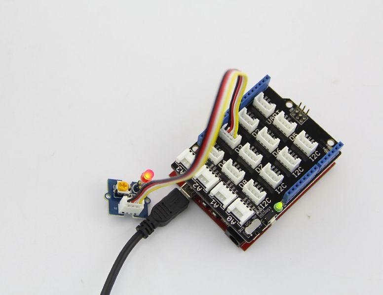
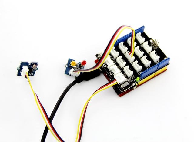
Grove – light Sensor
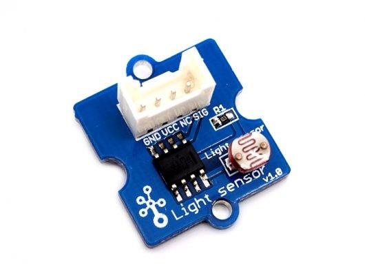
Light sensor, also known as the photosensitive resistor (LDR). Usually the resistance of the light sensor decreases when increasing the light intensity of the environment.
Example
The following example shows how the indicator illuminates when the light level falls below a set threshold:
File -> Sketchbook -> Grove_Light_Sensor
Tips
The output of the analog light sensor has a range from 0 to 1023, but is not linear relative to light intensity of the environment.
Detailed data on the use of the light sensor Grove you will find at the following link: Grove - Light Sensor
Grove – Button
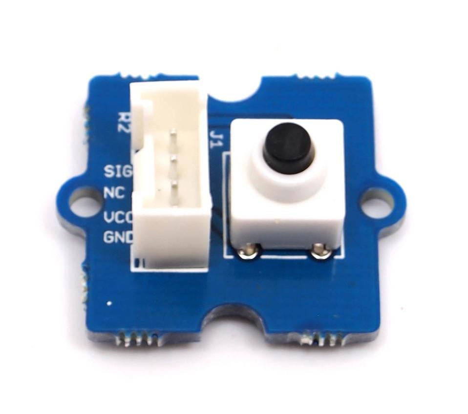
This version has one independent button, which is implemented using resistor podciągającego. Button Grove works with a microcontroller as a digital input. The button has a connector for signal SIG, NC is not used in this module.
Example
The following example shows how to enable or disable the led with the button:
File -> Sketchbook -> Grove_Button
Tips
Button short, this means that it is automatically raised again when pressed. Goes high when pressed and low when released.
Grove – Servo
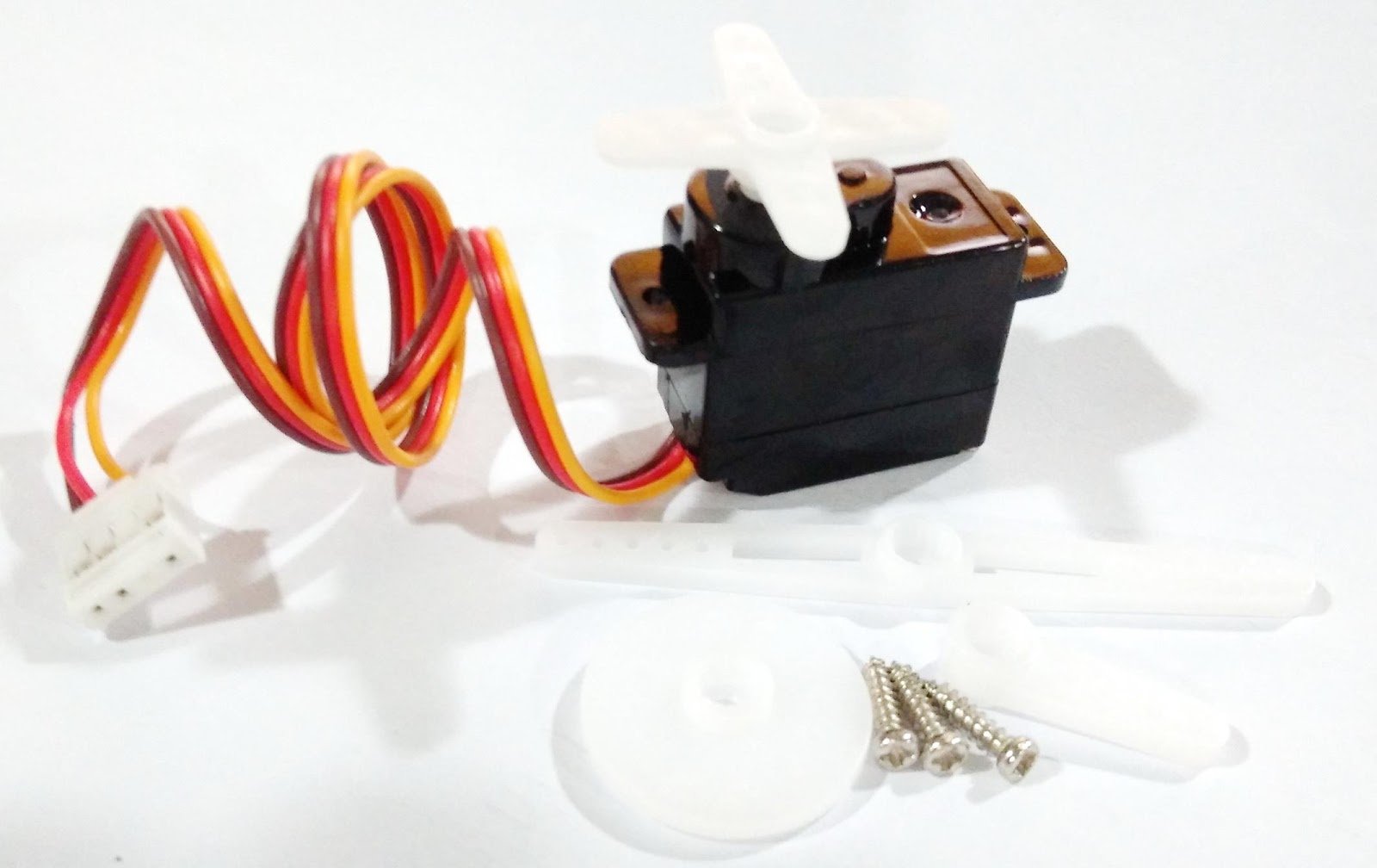
This engine, whose location can be precisely controlled.
Example
We have prepared an example that illustrates how to use a potentiometer for position control servo:
File --> Album --> Servo
Tips
Servo Grove offers its guests the build options for a variety of purposes: they can be used to drive a small fan, the removal of an object or to follow either clockwise or counterclockwise.
Examples of projects
1. Mug with flowers
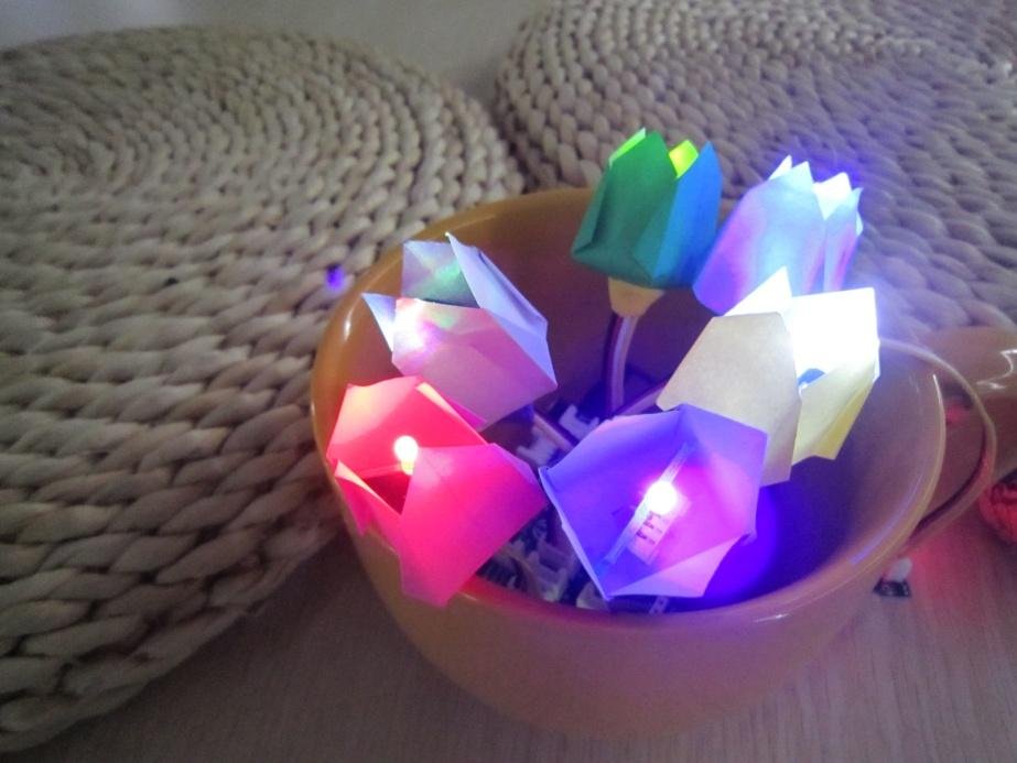
Description
Or beautiful flowers help You to relax? This design is made of LEDs and one sensor. When you touch the sensor the led will glow a nice warm light.
Parts list:
1. Arduino x 1;
2. Grove – base Module Base Shield x 1;
3. Grove – LED x 6;
4. Grove – touch Sensor x 1;
5. A piece of colored paper 6x6cm x 6;
6. 9V battery and 9V battery x 1.
Note
Select the number of LEDs depends on You. Basic kit includes three LEDs, but you can increase their number depending on the size of Your glass. In this example, we use of large cups, so we added three additional diode.
Instructions
1. Make paper flowers
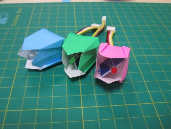
Select any template colors of origami and execute it. A Google search will definitely help You find the right, in the end, there are so many fans of origami that are happy to share their creations via the Internet.
In this example we chose a template of a Tulip, but, sunflowers, roses, or lilies too, of course, perfect.
When placing the colors, remember that at the bottom of the bowl, leave a small opening through which passes the cable.
2. Installation
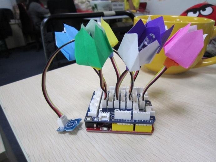
With a cable 10 cm connect the flowers and the sensor module base grove. Then put the following code in the controller.
void setup()
{
 pinMode(2, OUTPUT);
 pinMode(4, OUTPUT);
 pinMode(6, OUTPUT);
 pinMode(7, OUTPUT);
 pinMode(11, OUTPUT);
 pinMode(13, OUTPUT);
 pinMode(9, INPUT); //pin of touch sensor
}

void loop()
{
 int switchState = digitalRead(9);
 if (switchState == HIGH)
 {
 digitalWrite(2, HIGH);
 digitalWrite(4, HIGH);
 digitalWrite(6, HIGH);
 digitalWrite(7, HIGH);
 digitalWrite(11, HIGH);
 digitalWrite(13, HIGH);
 }
 else
 {
 digitalWrite(2, LOW);
 digitalWrite(4, LOW);
 digitalWrite(6, LOW);
 digitalWrite(7, LOW);
 digitalWrite(11, LOW);
 digitalWrite(13, LOW);
 }
 delay(100);
}
3. Food and laying in a circle
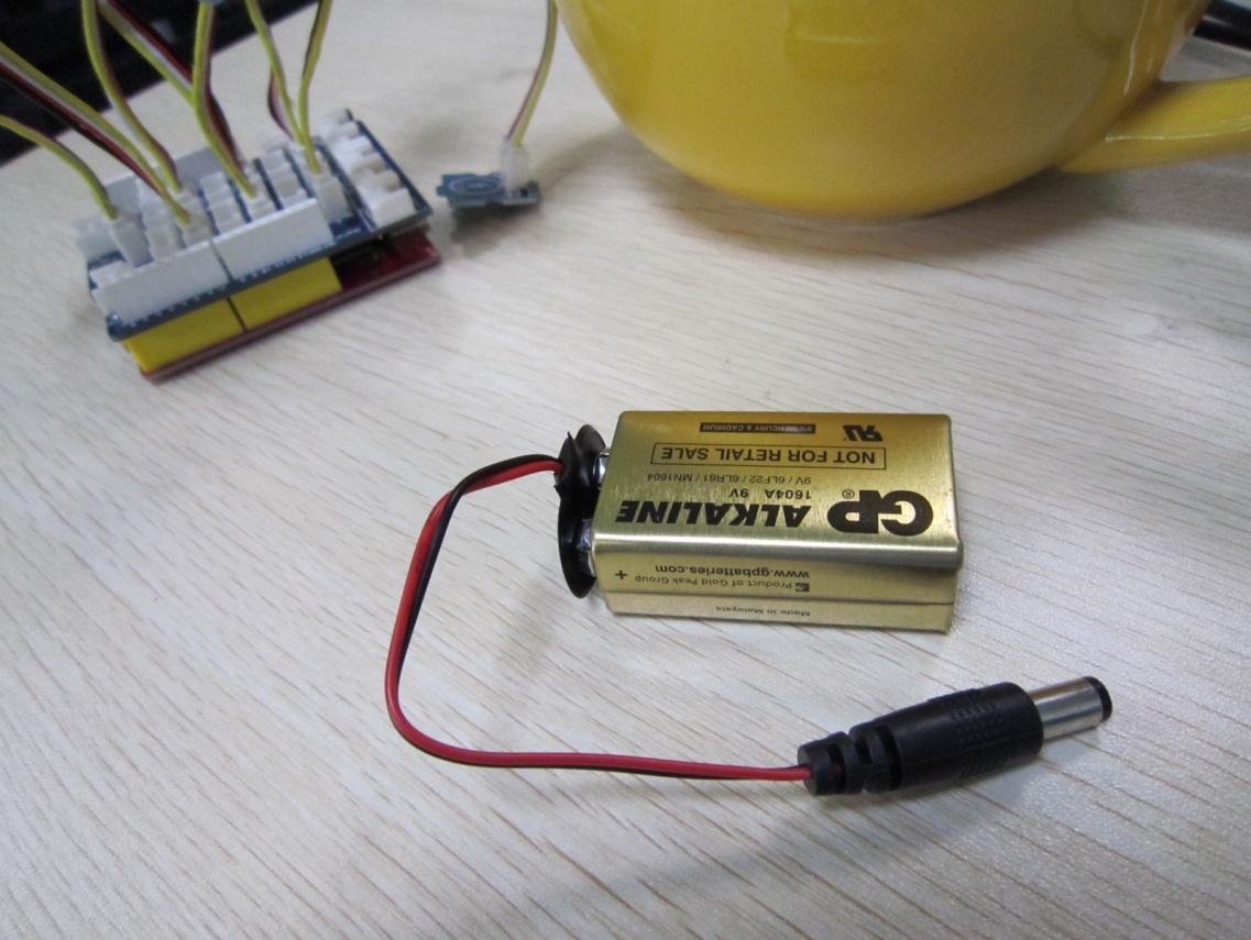
Use a 9V battery to power colors. Now it's time to set the flowers in the circle and the project is finished! Now every day you can delight you with the view of beautiful flowers!
2. Hi!

(downloaded from think.bigchief.it)
Description
And You, as you're with your friends? These men founded the paper back and nodding in greeting. See how you can make moving paper toys using a set of Grove!
The list of required parts
1. Arduino x 1;
2. Grove – base Module Base Shield x 1;
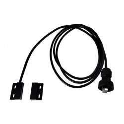
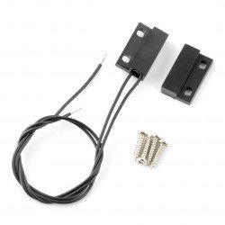
3. Grove – Magnetic switch x 1;
4. Grove – vibrating Module x 1;
5. Paper men x 2;
6. Magnet x 1;
7. 9V battery and 9V battery x 1.
Instructions
1. Print the template
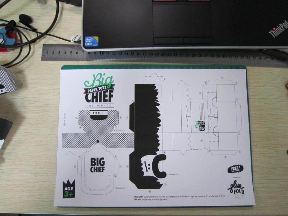
Find the template online. Please note that there was enough room to install the magnet or the magnetic switch together with the module sounds. As well as flowers origami in the Internet you can find hundreds of interesting patterns.
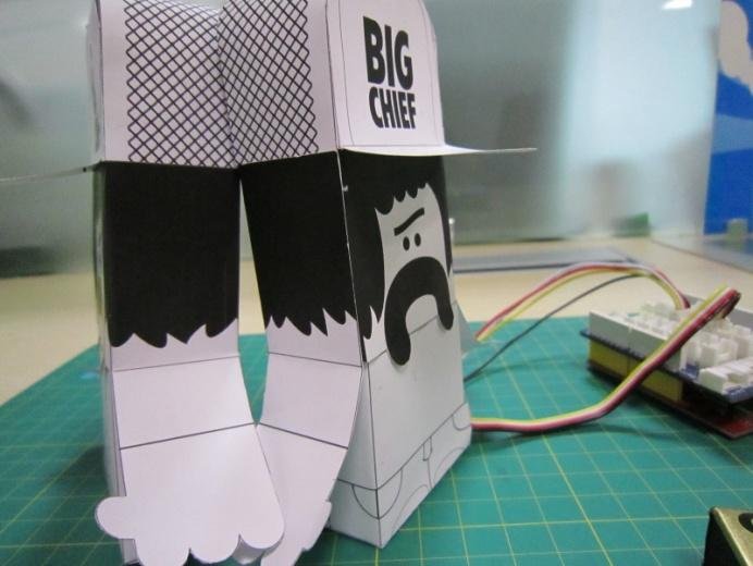
2. Complete action figure
Carefully cut the template out of paper. Only in this way You will be able to create a good and aesthetic toy. Mount the magnet behind the guy, it is possible for this purpose to use double-sided tape.
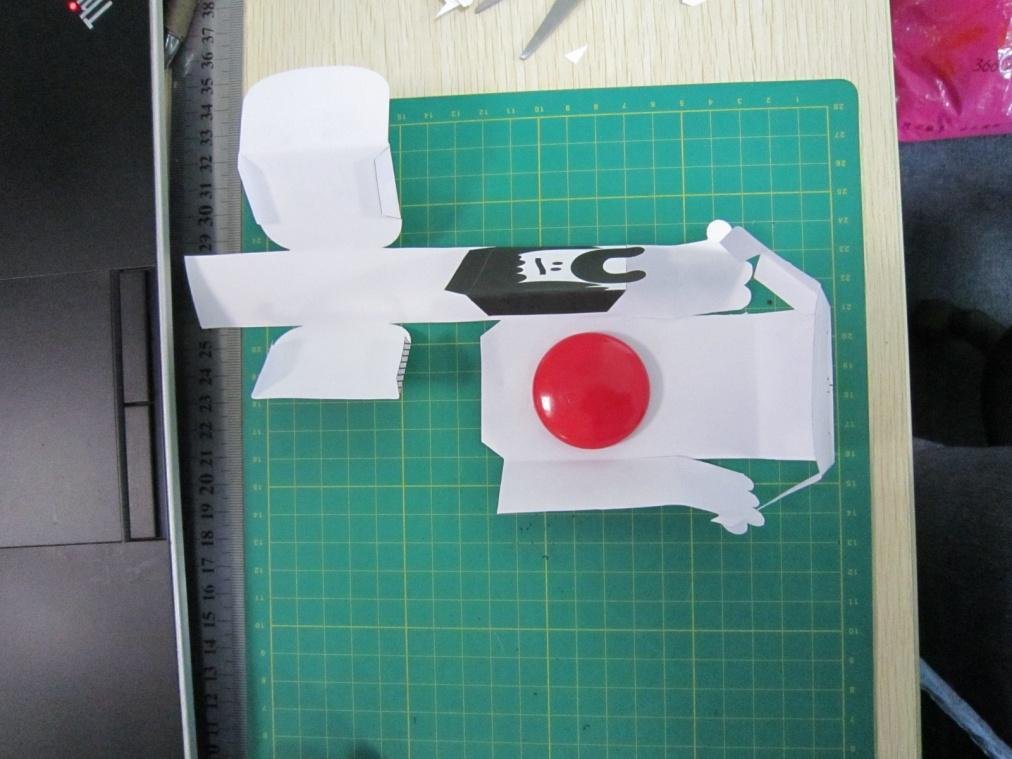
Behind the second guy trailers-magnetic circuit breaker, in the same place as the magnet on the ground. For legs, glue the module alive.
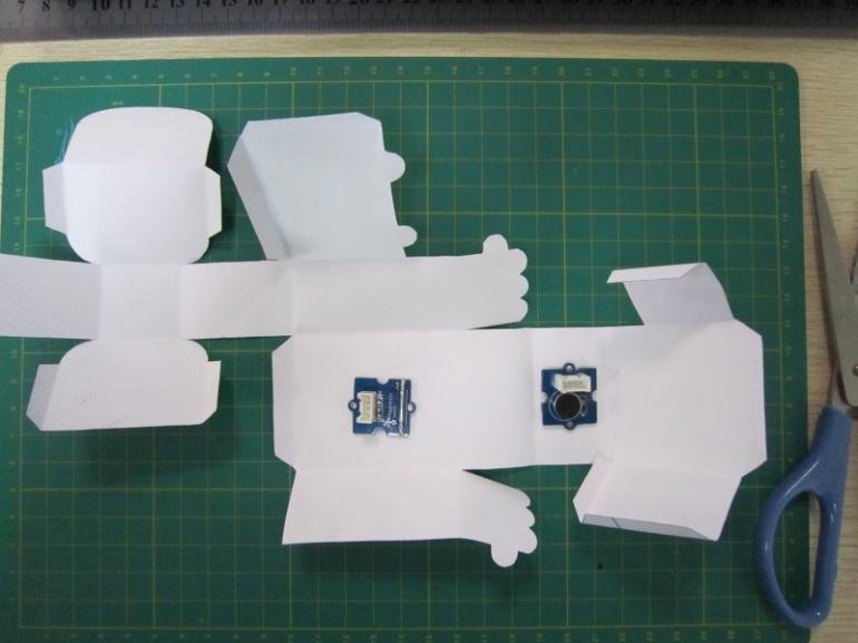
3. Assemble the template

Carefully assemble the templates by following the instructions on the printed template. To secure the wire Grove modules on the second ludziku. At this point, you must be willing two men, the same as in the picture above.
4. To download
Add the following code to your Arduino. Thus, it is said that the creatures will come to life!
void setup()
{
 pinMode(11, INPUT);
 pinMode(9, OUTPUT);
}

void loop()
{
 int sensorState = digitalRead(11);
 if (sensorState == 1) digitalWrite(9, HIGH);
 else digitalWrite(9, LOW);
 delay(100);
}
Kit feature
-
Standardized – thanks to its compact design, 4-pin connectors, screw holes and washer solder can reduce the negative impact on the environment, all parts can be reused in different projects
-
Small size – dimensions on a 2x2cm, connections, components for surface-mount and cable contacts with a pitch of 2.0 mm
-
Pleasant to use – easy connection, many extensions, elements for self-Assembly, libraries, and code examples
-
Powerful - wide range of schemes, from the basic (button, led) to professional sensor (gyro, compass), add how much you want the modules to be reusable
-
Social – a new idea, is chosen in the General election, the possibility of exchanging projects and instructions, profit sharing, borrowing and re-use