


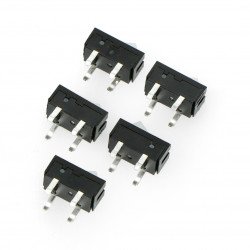


What's a stepper motor? How does the stepper motor work?
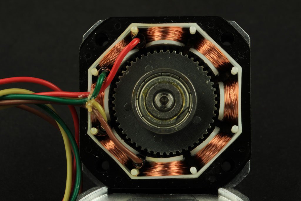
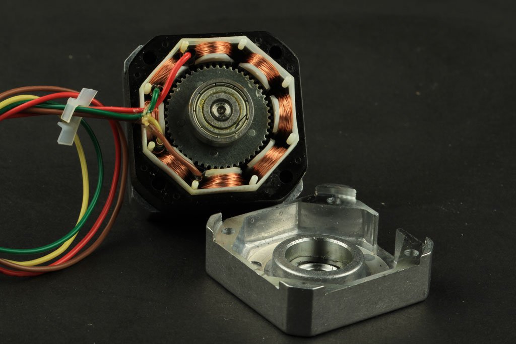
Construction of the stepper motor
Stepper motor - Construction and application
Stepper motors are direct current motors that move with specific strokes. They have numerous coils collected in groups called "phases". After powering each phase in turn, the motor will turn one step.
Using a computer, you can set the position of the bruise and/or control its speed. For this reason, they are selected for many applications to supervise the precision of movement.
Stepper motors have different sizes and styles and electrical parameters. This guide will show you everything you need to know when selecting the right motor for you.
Stepper motor - Diagram:
4-phase single-pole motor
Animation from Wikipedia
Where can you use stepper motors?
- Positioning - these motors move with specific, repetitive strokes, so they are best for applications that require precise positioning, such as 3D printers, CNC , camera platforms and X-Y plotters. Some disc drivesalso use stepper motors to position electromagnetic heads.
- Speed control - Precise increase in motion allows for excellent control of rotary motion in the automation and robotics process.
- Low torque- Standard DC motors do not have high torque at low speed. However,the stepper motor has maximum torque at low speed, so it is a good choice if you are looking for a motor with the above mentioned speed and high precision.
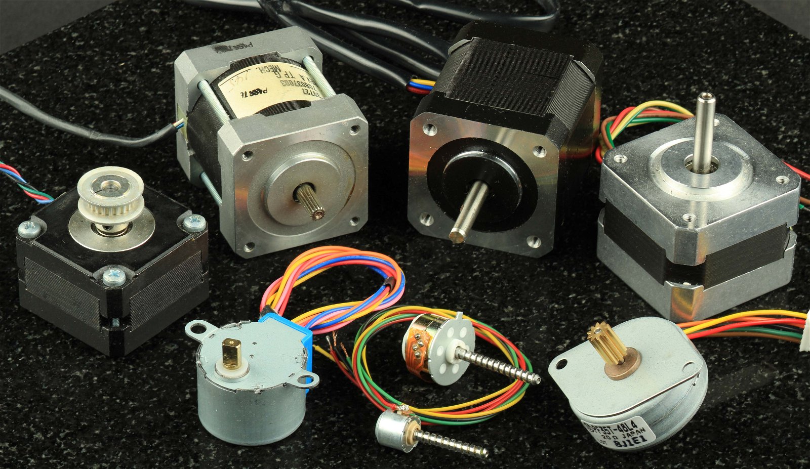
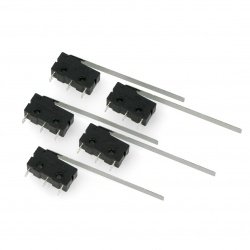
Stepper motors of different designs
What are the limitations of stepper motors?
- Low efficiency - the current consumption of the stepper motor is independent of the load. They consume the most power when they are not running. For this reason, they tend to heat up.
- Limited high torque- stepper motors have lower torque, not at low but at high speeds. Some of them are optimized to have high speeds and must be paired with a suitable controller to achieve them.
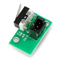
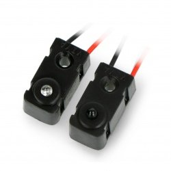
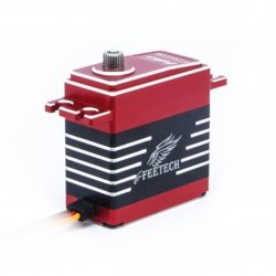
- No feedback - Unlike servo motors , most stepper motors do not have integral positioning feedback. However, excellent precision can be achieved by switching on the "open loop". Limit switches or home sensors are usually needed for safety and/or to establish a reference position.
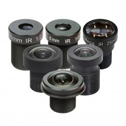
Types of stepper motors
There is a wide range of stepper motors, some of which require very specialised controllers. In our guide, we will only focus on those that can work with commonly available controllers. These are: permanent magnet motor or hybrid motor, bipolar two-phase or four-phase unipolar motor.

Types of stepper motors
Stepper motor - Engine size
One of the first things to consider is the work the engine has to do. You can guess that bigger ones can deliver more power. Stepper motors may be smaller than a nut, but they are also as big as NEMA 57.
Most of them have a nominal torque value. This is what you have to watch out for when deciding if the motor has enough power.
NEMA 17 is a typical size motor that is used in 3D printers andsmaller CNCmilling machines. The small motors are used in many robotic and animatronic projects. Larger NEMA motors are typically used in CNC machines and are used in industry.
The NEMA numbers indicate the standard faceplate dimensions for motor assembly. They do not define other motor parameters. Two different NEMA 17 motors have completely different electrical or mechanical specifications. They are not interchangeable.
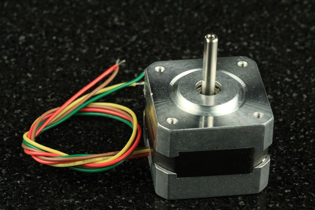
NEMA17 stepper motor
Step counter
The next thing to mention is the required positioning resolution. The number of steps per revolution ranges from 4 to 400. Commonly available step counters are 24, 48 and 200.
The resolution is often expressed in degrees per step. The 1.8° motor is the same as the 200 steps per revolution motor.
The compromise for high resolution is speed and torque. Motors with a large number of steps work better at lower rpm. Faster speed results in lower torque.
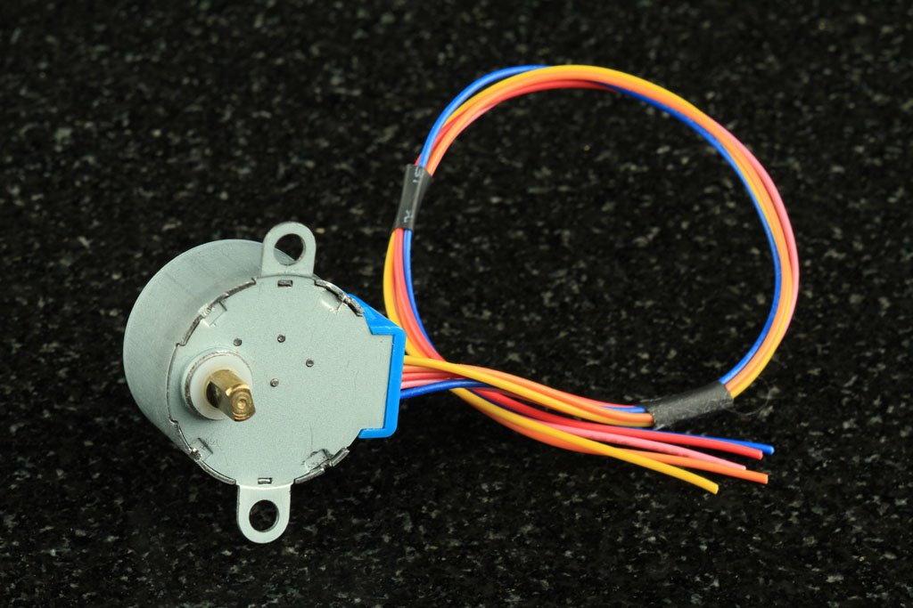
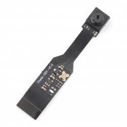
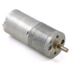
Small stepper motor
Gearbox
Another way to achieve high resolution positioning is to use a gearbox. The effect of using a 32:1 gearbox on theoutput of an 8-step motor will be a 512-step motor.
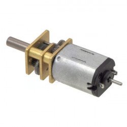
The gearbox will also increase the motor torque. Some small stepper motors with a gearbox have amazing torques. But the compromise of course is speed. Geared stepper motors are usually used in low-speed projects.
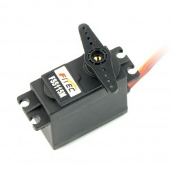
Idler stepper motor
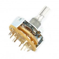
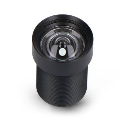
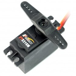
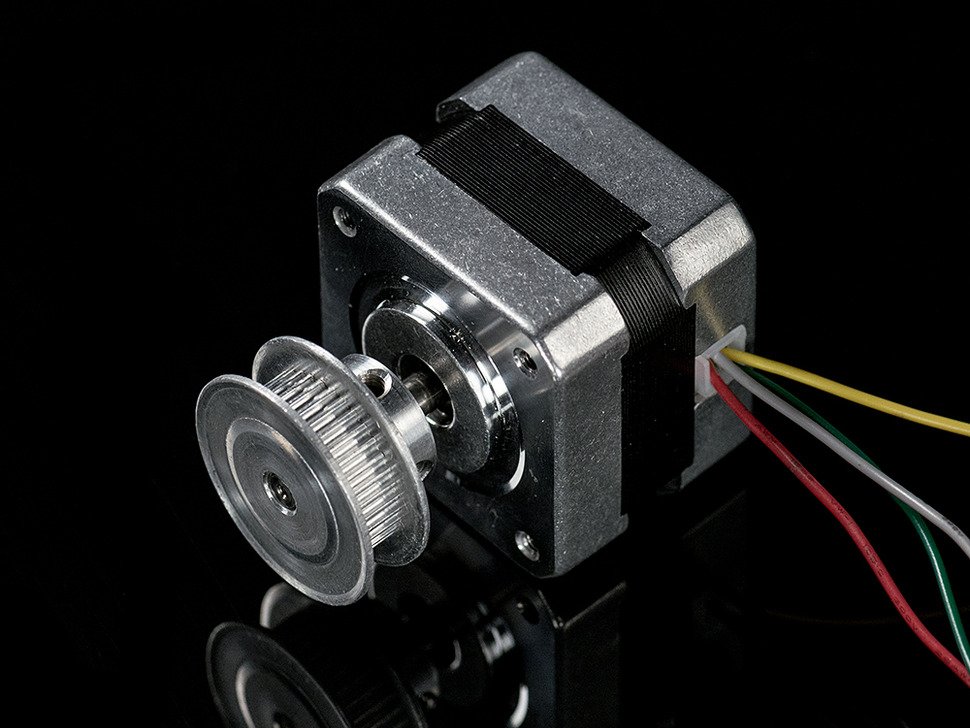
Shaft style
The next issue worthy of your attention is the interaction of the engine with the rest of the drive train. Shaft motors are available in different styles:
- Shaft "D" or round - these are available in various standard diameters. Many pulleys and gears and shaft couplings are designed to fit. The flattened side of the "D" shaft prevents slippage. They are precisely the right choice for high torques.
- Toothed shaft - some shafts have milled gear teeth. They are usually designed to work with modular gear sets.
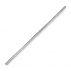
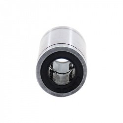
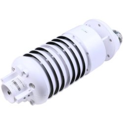
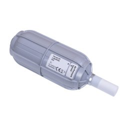
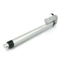
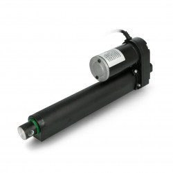
- Screw shaft- Screw shaft motors are used to build linear actuators. Their miniature versions are head positioners in disc drives.
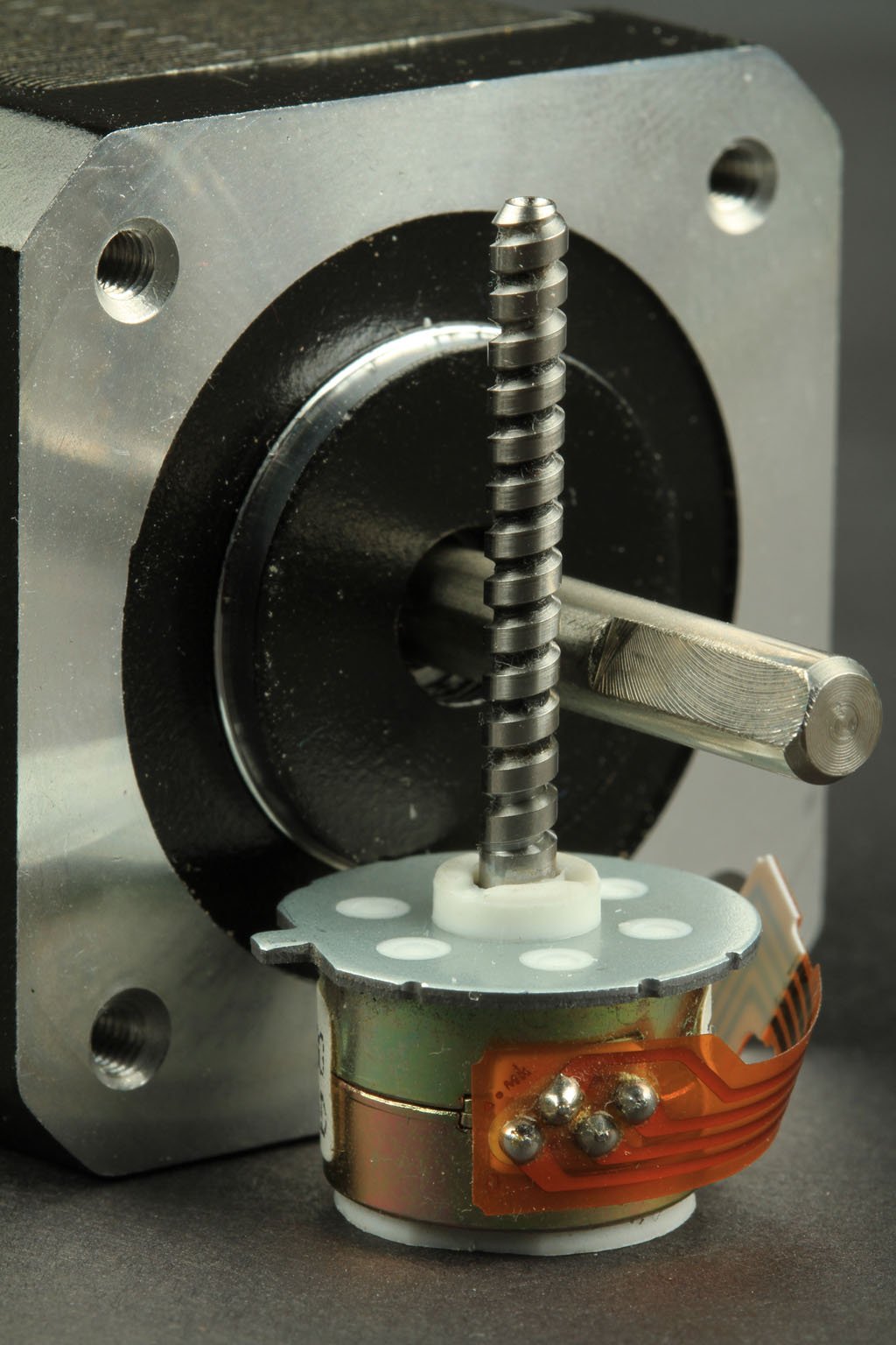
Stepper motors with different shaft types
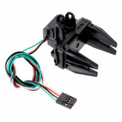
Wiring
There are many types of cabling in stepper motors. We will focus on those that can be driven by commonly available controllers . These are permanent magnet or hybrid motors, wired as 2-phase bipolar or 4-phase unipolar.
Stepper motor wiring
Coils and phases
The stepper motor can have any number of coils. However, they are combined into groups called "phases". All coils in a phase are powered together.
Stepper motor phases
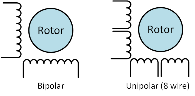
VS bipolar stepper motor VS bipolar stepper motor
The unipolar motor (unipolar motor)always supplies the phases in the same way. One "common" wire will always be with a negative charge. The other, will be with a positive charge. These controllers can be implemented with simple transistor circuits. Its disadvantage is that it has less torque, because only half of the coils can be powered simultaneously.
The bipolar controller (bipolar motor)uses the H bridge system to reverse the current flow using phases. By supplying them with alternating polarity, all coils will start to operate while turning the motor on.
The two-phase bipolar motor has 2 groups of coils. The 4-phase unipolar motor has such groups. The 2-phase bipolar motor will have 4 wires - 2 for each phase. Some motors have flexible wiring to allow the motor to start in unipolar or bipolar mode.
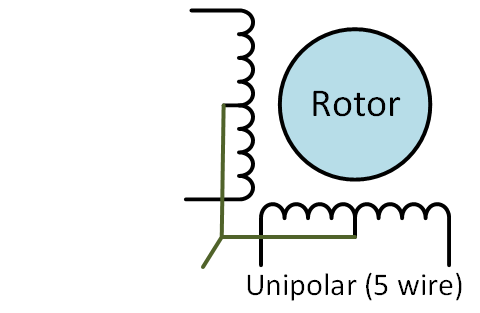
Unipolar, 5-wire
5-wire motor
All common coil wires are tied inside and lead out as 5 wires. This motor can only operate in unipolar mode.
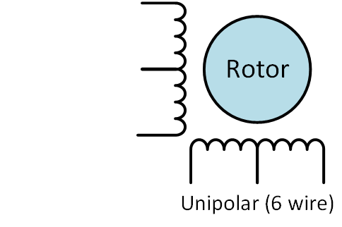
Unipolar, 6-wire
6-wire motor
It only connects the common wires of 2 paired phases. The wires can be connected to form a 5-wire unipolar motor.
You can also use the motor as bipolar without paying attention to the wires.
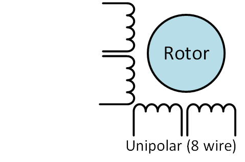
Unipolar, 8-wire
8-wire motor
This unipolar engine is the most versatile of all. It can be driven in many ways:
- 4-phase unipolar- all common cables are connected - just like a 5-wire motor.
- 2-phasebipolar in series - the phases are connected in series - as with a 6-wire motor
- 2-phase bipolar parallel- the phases are connected in parallel. This results in half the resistance and inductance - however, it requires twice as much current to start. The advantage of this wiring is higher torque and maximum speed.

Stepper motors combination
Stepper motor control
Stepper motor controllers
Stepper motors - Control - The stepper motor is a little more complicated to use than a standard DC brush motor. Stepper motors must have their own controller to be able to supply the phases in the right order to drive the motor in this way.
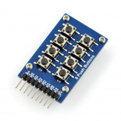
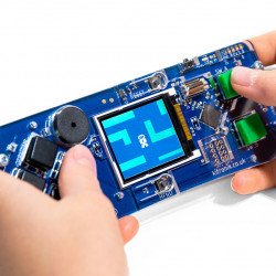
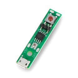
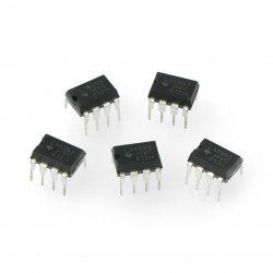
Transistors
Stepper motor - Control - Simple unipolar controller
The simplest type of controller can be built with a small number of transistors. They are switched on and off in a sequence to power the phases and switch on the motor. Construction of such drivers is relatively cheap, but they only work with unipolar engines. You can find a tutorial on how to make such a driver on the Arduino website.
| Guide for controlling the unipolar stepper motor |
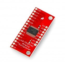
Stepper motor controller - integrated circuit
Simple two-channel bridge controller H
Using a bipolar motor requires 2 full H-bridges for the current to return to phases. But building them from scratch can be difficult. There are many H-bridge systems available that can make this easier.
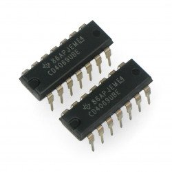
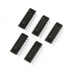
The L293D is one of the most popular and economical systems. It can be found at the base of most first generation disc motors.
In the Arduino Science System, you will find a great tutorial on how to use L293Dwith Arduino:
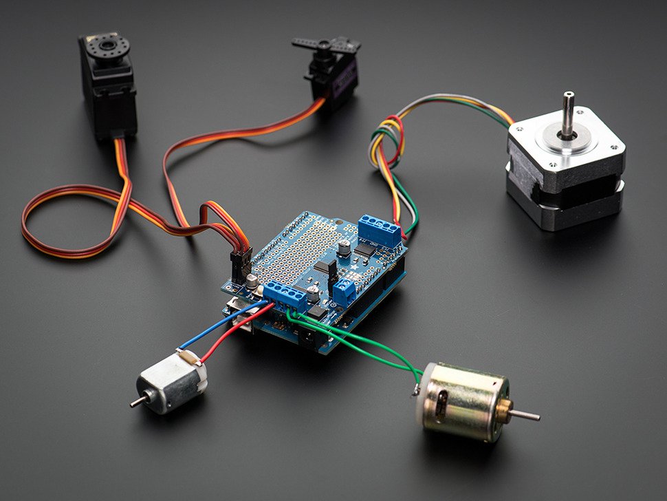
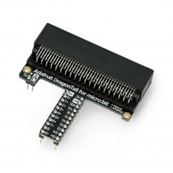
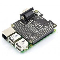
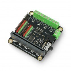
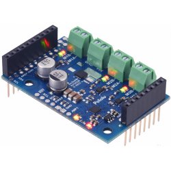
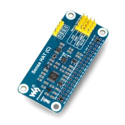
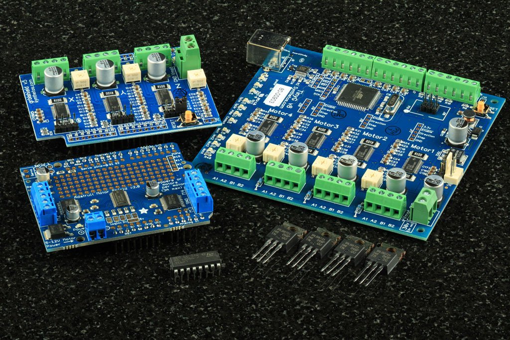
AdafruitMotor Shield V2 overlaywith Arduino and connected motors
Adafruit Motor Shield V2 overlay
TheAdafruit Motor Shield V2 is a major advancement over the basic L239D-based controllers. V2 uses two TB6612 MOSFET controllers. Compared to L293D, TB6612 offers twice the current efficiency and much lower voltage drops, which improves the use of the stepper motor.
With 2 controls and 4 H-bridges, each cap can drive up to two motors. The controls are connected via the PWM control with I2C interface. This frees up many GPIO pins that can be used for something else, and the overlays can be stacked on top of each other. You can stack up to 32 overlays that will control up to 64 motors with 2 IO pins.
You will find all the information about this driver in the Teaching System.

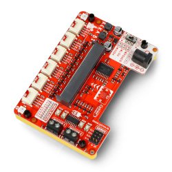
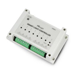
CNC Controller
Advanced CNC controllers
The gShield and TinyG CNC control boards will bring you closer to stepper motor performance on an industrial level. They are distinguished by their direct current controllers called "chopper". They can be adjusted to provide maximum torque and motor speed.
TinyG CNC has a G-code interpreter program on board and 4 motor outputs. Thus, small and medium 4 axis CNC machines have a complete built-in solution.
However, these advanced high performance boards are more complex and are recommended for more experienced users.
Information about these boards and their performance can be found in the TinyG Wiki and the Synthetos forums.
Matching the controller to the stepper motor
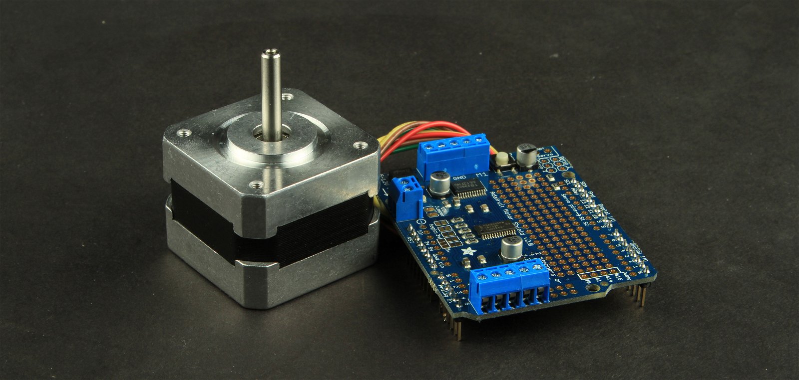
Stepper motor connected to the controller
Now we come to the most important part: making sure that themotor and controllerare compatible.
The result of their mismatch can be unsatisfactory performance and, even worse, damage to the engine and/or controller.
If you make the wrong choice, you may be affected:
Read the controller's parameters
The two most important parameters of the controller are
- Voltage - maximum voltage that can be supplied to the motor
- Continuous current - maximum continuous current that can be supplied to the motor
|
Current peaks do not apply to stepper motors. Always use the rated continuous current |
How to check the stepper motor? - Get to know the parameters of the engine
You must also know the engine parameters. There are 2 important parameters:
- Amps per phase - this is the maximum current that the motor winding can handle without overheating
- Resistance per phase - this is the electrical resistance for each phase
The ratedvoltageis usually given. They are calculated using the two parameters above - but not always. It is better to calculate them yourself, also using the above factors, but in Ohm's Law.
Follow the law!
Stepper motor phases are inductive coils that are not subject to rapid changes in current flow. But at the end of each stroke, or when not in motion, they behave like a resistive load, and according to Ohm's Law.
The motor draws the most power when not running. Ohm's law allows you to use motor parameters to calculate the current needed by the controller.
Voltage = Current x Resistance
or
Current = Voltage / resistance
| These formulae should be strictly applied to all stepper motor controllers with continuous current. This also applies to motor covers V1 and V2 from Adafruit, and virtually all other L293D-based controllers. |
However, some motors have very low coil resistance. Therefore, the use of these formulas will result in a voltage of less than 5 volts and performance will not be satisfactory. This type of motor does not fit into a constant voltage controller and requires a more specialized controller.
You want to break the law?
As far as the Ohm's Law is concerned, nobody's ever succeeded. Don't even try it. It's gonna end badly. However, there are other laws here. The Laws of Lenz, Faraday and Ohm will help you make your engine more efficient.
Stepper motor coils produce a magnetic field when powered. According to Faraday's rightsthe changing magnetic field causes a current flow in the coil. And according to Lenz rightsthis current will flow in the opposite direction to the current producing a magnetic field. Such a reverse current is known as the "Reverse Electromotive Force" orreverse EMF.
This force increases the "impedance" or makes the resistance of the coil effective. So the Ohm's law stillapplies - but only to impedance, not to simple phase resistance. At thebeginning of each stroke, impedancelimits the flow of current through the coil.
The CNC controller
Chopper drives
The Chopper drive, or continuouscurrentdrive, balancesthe EMF backstop by driving the motor with higher voltage. Driving stepper motors several times the rated voltage using a chopper drive is normal.
At such high voltages, safety must be taken care of. For this purpose, the chopper drive also monitors the current supplied to the motor and "cuts" it before it exceeds the originally set level.
Starting with higher voltages, our controller is able to supply more current to the coils at the beginning of the stroke, increasing the available torque. Additionally, it allows for higher maximum speeds.
You need to understand the operation of the motor and controller if you want to select a chopper controller and configure it with a specific motor.
FAQ
Will this engine work with my cap?
You must check the parameters of the motor and the controller. Then go to the paragraph "Matchingthe controller to the stepper motor" and see if they are compatible.
NEMA 17 should work... right?
NEMA size only defines the size of the mounting faceplate. To find out if it is compatible, you need to know the electrical parameters of the motor.
Stepper motor selection - What size motor should I choose for my project?
Most motors have torque parameters - usually in inches / ounces or newtons/ centimeters. One newton/inch means the motor can exert a force of one newton per centimetre from the center of the shaft. For example, it can withstand one newton of force using a 2 centimeter diameter pulley.
When calculating the torque, make sure to take into account the additional force that is required for acceleration and to overcome friction. More torque is needed to lift something than to maintain it.
If your project requires high torque but low speed, check the stepper motor with gearbox.
How will I connect the motor to the cap?
Check the motor specifications, if you have one.
Stepper motor power supply - Will this power supply work with my motor?
First, make sure it does not exceed the rated voltage for the motor controller.* You will start it at low voltage, but it may have less torque.
*This only applies to constant current controllers.*
Types of stepper motors
Source: https://learn.adafruit.com/all-about-stepper-motors