


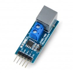


Arduino in combination with rain sensor YL-83
This short tutorial shows how to operate the rain sensor via the Arduino board.
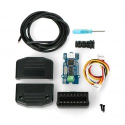
The following elements are used in the example:
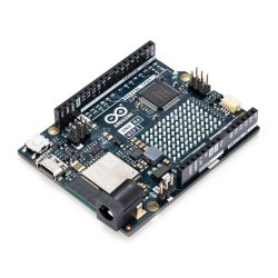
- Arduino Uno
- Rain :-)
Connection
The module is powered directly from Arduino, so we don't need an external power source. Pins are connected according to the table:
| Arduino Pin | Pin Sensor |
|---|---|
| 5 V | VCC |
| GND | GND |
| pin A0 | A0 |
| pin 2 | D0 |
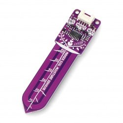
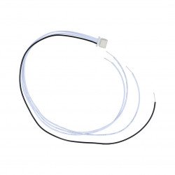
The other two pins from the sensor module are connected to the measuring probe using the supplied cable as shown in the diagram below:
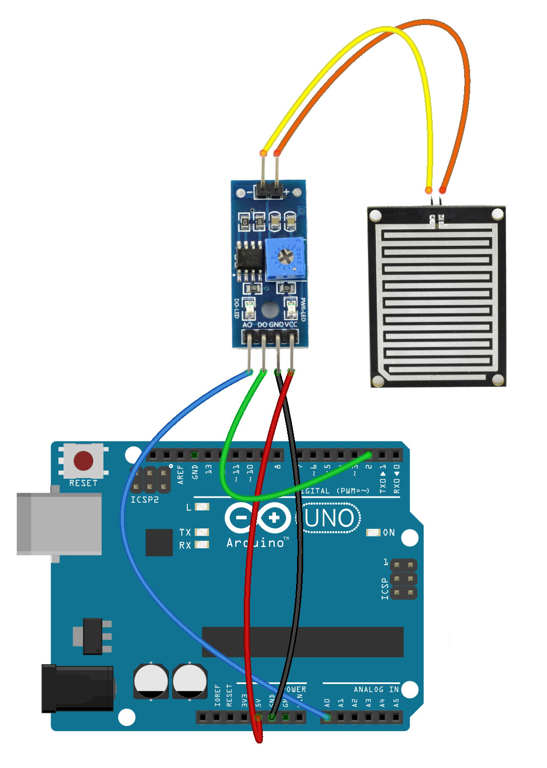
Rain sensor connection diagram.
Operation
Output D0 works digitally. By default, it is in high state, but when precipitation is detected, it goes to low state. The sensitivity can be adjusted with a built-in potentiometer. Output A0, on the other hand, generates an analogue signal and reduces the voltage value as the rainfall increases (it is inversely proportional to the intensity of the rain). In the example, we will use a simple program that will continuously display the values read from A0 and D0 on a serial monitor.
int sensor_A0 = A0; // connection from A0 on the sensor to A0 on Arduino
int sensor_D0 = 2; // connection from D0 on sensor to pin 2 on Arduino
int value_A0; // variable for value A0
int value_D0; // variable for value A0

void setup() {
  Serial.begin(9600); // run the serial monitor
 pinMode(2, INPUT); // setting pin 2 as input

}

void loop() {

 value_A0 = analogRead(sensor_A0); // take value from A0
 value_D0 = digitalRead(sensor_D0); // downloading value from D0

 Serial.print("D0: "); // display on a serial monitor
 Serial.print(value_D0);
 Serial.print(" -- A0: ");
 Serial.println(value_A0);
 delay(200); // delay between readings
 }
The effects of the program can be seen on the screen below:
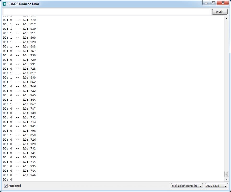
Serial screenshot of the monitor.